After reading this chapter, you should be able to:
Distinguish between the global coordinate system (GCS) and the body coordinate system (BCS), and explain why the BCS origin is best placed at a fixed geometric point on the vehicle rather than at its centre of gravity
Describe the pose of a rigid body in terms of the position of the BCS origin and the orientation of the BCS relative to the GCS
Compare the four common parametrizations of orientation — Euler angles, axis-angle, quaternions and the rotation matrix — and state the advantages and limitations of each
Explain why rotations do not commute, and determine the effect of changing the order in which a sequence of rotations is applied
Derive the rotation matrix for the ZYX Euler angle sequence as a product of the three elemental rotation matrices, and use its orthogonality to transform vectors between the BCS and the GCS
Identify the gimbal lock orientations of a given Euler angle sequence, and explain why the degeneracy lies in the representation of the orientation rather than in the physical motion of the body
Relate the Euler angle and axis-angle parametrizations of the same orientation, and recover the axis \(\hat{a}\) and angle \(\Theta\) of rotation from a rotation matrix
Derive the relationship between the body-frame angular velocity and the Euler angle rates, and identify the orientations at which this transformation becomes singular
Assemble the kinematic equations of a rigid body relating the rate of change of the pose to the body-frame translational and angular velocities
4.1 Motivation
Motion of a marine vehicle (assumed to be rigid) requires the knowledge of the pose and velocities of the vehicle as a function of time. Vehicle motion is governed by both kinematics and dynamics. Kinematics refers to the study of the motion of a rigid body without considering the forces and moments that cause the motion. The study of the forces and moments acting on the vehicle that cause its motion is known as dynamics. This chapter will focus on the kinematics of a rigid body.
4.2 Coordinate Systems
The pose and velocity of a rigid body is always defined with respect a coordinate frame of reference. Therefore, coordinate systems need to be defined before the description of motion of a rigid body is possible. Two right hand coordinate systems are defined as follows:
Global Coordinate System (GCS): This is an inertial coordinate system fixed to the Earth. The usual convention when considering vehicle’s maneuvering motions is to consider a East-North-Up (ENU) frame of reference with origin on the surface of the earth.
Body Coordinate System (BCS): This is a coordinate system fixed with the vehicle. As the body undergoes motion the BCS also moves with it. Thus BCS is not an inertial frame of reference. Usual convention is to choose the x-axis of BCS to be along the length of the vehicle, z-axis pointing upwards and y-axis following the right hand rule. For a ship floating in even keel, this will result in x-axis along the longitudinal direction (from aft to forward) of the ship, y-axis pointing towards port direction and z-axis pointing vertically up. The origin of the BCS may be chosen either to be at the center of gravity or a geometric point on the vessel. In general, the center of gravity of the vehicle would change depending on the vessel’s loading condition (fully loaded or ballast loaded), consumption of fuel during the voyage and due to loading or unloading of cargo at ports. Thus, it is better to choose a geometric point on the vehicle that does not change with time as the origin of BCS. The intersection of midship section, centerline and fully loaded waterline is a good choice for the origin of BCS. For underwater vehicles the geometric center of the vehicle may be chosen as the BCS origin.
The above described choice of BCS and GCS origins and their orientations are the generally used convention. One can choose the origins and frame orientations arbitrarily as long as they are maintained consistently. For ease of understanding, the convention described above will be followed in this text.
Both coordinate systems are illustrated in Figure 4.1. The origin of GCS is denoted as \(O_0\) and its axes are denoted as \(X_0Y_0Z_0\). The coordinates of a point in GCS frame will be denoted by \((x_0, y_0, z_0)\). The origin of the BCS frame is denoted by \(O'\) and its axes are denoted as \(X'Y'Z'\). The coordinates of a point expressed in BCS frame will be denoted by \((x, y, z)\).
(a) Body Coordinate System (BCS)
(b) Global Coordinate System (GCS)
Figure 4.1: Coordinate Systems
The unit vectors along the x, y and z axes of GCS are denoted as \(\hat{i}_0\), \(\hat{j}_0\) and \(\hat{k}_0\) respectively. Similarly the unit vectors along the x, y and z axes of the BCS are denoted as \(\hat{i}\), \(\hat{j}\) and \(\hat{k}\) respectively.
4.3 Pose of a Rigid Body
The pose of a rigid body can be described in terms of the above defined coordinate systems. The translation of the body is described as the position vector from the GCS origin to the BCS origin expressed in the GCS frame. In Figure 4.1 we can see that position vector of the origin of BCS in the GCS frame is given by \(\eqref{eq-gcsbcs-posvec}\).
The three parameters \(x_0\), \(y_0\) and \(z_0\) describe the translation of the body. However, as the BCS moves with the body, it may be in a different orientation as compared to the GCS at any particular instant. This means that the axes of BCS need not be parallel to the axes of GCS. Thus, the orientation also needs to be known to characterize the motion of the vehicle completely. The orientation can be described using one of the following ways:
Euler angle representation: The orientation between two coordinate frames is expressed as a sequence of three rotations in a specified order. Unlike translations, rotations are not commutative and thus a specific order needs to be maintained. The non-cummutative property of rotations can be seen from Figure 4.2 where two \(90^\circ\) rotations are applied in two different orders. The first approach (left subplot) applies a \(90^\circ\) rotation about the z-axis followed by a \(90^\circ\) rotation about the new x-axis. The second approach (right subplot) interchanges the rotation order - a \(90^\circ\) rotation about the x-axis is applied first and then a \(90^\circ\) rotation is applied about the new z-axis. Note that when each rotation is taken about the body’s own new axes, the matrix of the rotation applied first stands to the left. The orientations of the new coordinate frames are completely different when the order of rotations is swapped. The Python code used to generate the results showns in Figure 4.2 is shown below, and the interactive tool at the end of this section lets you vary the axes and the angles yourself. Euler angles will be described in detail in Section 4.4.
Figure 4.2: The solid line represents the GCS orientation and the dotted line represents the BCS oreintation. For GCS, x-axis is shown in red, y-axis in green and z-axis in blue. For BCS, x-axis is shown in cyan, y-axis in magenta and z-axis in yellow. Applying 90 degrees rotation about z-axis followed by 90 degrees rotation about the new x-axis leads to the orientation shown in the left subplot. Interchanging the rotation order leads to the orientation shown in the right subplot.
Axis-angle representation: The orientation between the two coordinate frames (GCS and BCS) can be described as a single rotation about an axis of rotation that results in GCS being oriented along the BCS. The rotation is parametrized by the unit vector \(\hat{a}\) along the axis about which the rotation is performed and the magnitude of the angle of rotation \(\Theta\). This parametrization has three independent parameters. The axis being a unit vector has two independent parameters with the third parameter being constrained by the property that the vector \(\hat{a}\) is a unit vector. The third independent parameter is the angle of rotation \(\Theta\).
Quaternion: In this parametrization, the orientation between two coordinate frames (GCS and BCS) is characterized by four parameters. The parameters of a quaternion are closely related to the axis-angle representation parameters \(\Theta\) and \(\hat{a}\). The first parameter of a quaternion is \(\cos(\frac{\Theta}{2})\). The other three parameters are the components of the vector \(\sin(\frac{\Theta}{2}) \hat{a}\). The Quaternions have the primary advantage of being numerically stable, compact and efficient as compared to the other rotation formalisms. However, in contrast to the Euler angles or axis-angle representation they have one extra parameter. Quaternions have found applications in several fields including robotics, space navigation, computer vision, flight dynamics etc.
Rotation Matrix: The orientation between the two coordinate frames can also be characterized by a \(3 \times 3\) rotation matrix that has \(9\) parameters. The rotation matrix projects the vectors from one frame into another. The rotation matrix \(\boldsymbol{R}\) to project vectors from BCS to GCS is given by \(\eqref{eq-rotm-def}\). The rotation matrix to project vectors from GCS to BCS is given by the transpose of the rotation matrix denoted by \(\boldsymbol{R}^T\).
Consider a vector \(\vec{p}\) expressed in BCS. The same vector expressed in GCS \(\vec{p}_0\) is then given by premultiplying the vector \(\vec{p}\) by the rotation matrix \(\boldsymbol{R}\) as shown in \(\eqref{eq-rotm-bcs-to-gcs}\).
Some of the other formalisms of rotation in 3D space can be found here.
Each of the rotation formalisms have their own advantages and disadvantages. The rotation matrix has more parameters than any of the other formulations. Quaternions, on the other hand, represent the most compact formulation and are also numerically stable. However, they are difficult to intuitively appreciate. On the contrary, the Euler angles are most intuitive to understand and only have \(3\) parameters. The Euler angle formulation suffers from singularity at two specific orientations. This phenomenon is known as gimbal lock and will be explored more in Section 4.4.1. For marine vehicles like ships, if the order of rotation of the Euler angles is chosen well, the gimbal lock orientation is not encountered in regular operations. Thus for ships, Euler angles have become a popular approach as they are intuitive to understand.
Interactive Simulation: Order of Rotations
Figure 4.2 makes the point about non-commutativity with two static pictures. The tool below lets you make that point yourself, for any pair of axes and any pair of angles. Two identical ships start aligned with the GCS, each standing on its own tinted pedestal on which a faint copy of the fixed GCS triad is drawn. The body axes are painted on each ship (bow \(+x\) in red, port \(+y\) in green, up \(+z\) in blue) so you can watch the BCS peel away from the GCS. Drag with the mouse to orbit the view.
Both ships then perform exactly the same two rotations, in opposite orders:
the blue ship (Sequence 1) turns first by \(\alpha\) about the first axis and then by \(\beta\) about the new second axis;
the orange ship (Sequence 2) performs the same two rotations the other way round.
A dark rod marks the axis each ship is turning about at that moment. Press Play both sequences and watch step 1 and step 2 run side by side. Note that in step 2 the rod is not along a GCS axis any more: each ship turns about its own newly rotated body axis, which is precisely why the two ships part company. The readout reports the single angle through which one final orientation would have to be turned to reach the other, so a value of \(0^\circ\) means the two orders agree.
Some things worth trying:
The default setting (\(90^\circ\) about \(Z\), then \(90^\circ\) about \(X\)) reproduces Figure 4.2. The two final orientations end up \(120^\circ\) apart: the bow points along \(+y\) in Sequence 1 and along \(+z\) in Sequence 2.
Set both axes to the same letter. The disagreement collapses to \(0^\circ\): rotations about a common axis do commute, and the angles simply add.
Shrink both angles to \(5^\circ\); the disagreement falls to \(0.44^\circ\). Doubling both angles to \(10^\circ\) very nearly quadruples it, to \(1.74^\circ\) — the disagreement grows with the product of the two angles, and so is second order in the rotation angles. This is why for small angular displacements the order can be neglected and angular displacements behave like ordinary (commuting) vectors, an approximation we will lean on when linearizing the equations of motion.
Set both angles to \(180^\circ\). The disagreement returns to \(0^\circ\), so the two orders can also agree at isolated special values without the rotations commuting in general. Keeping the first angle at \(180^\circ\) and setting the second to \(90^\circ\), on the other hand, gives the worst possible case of \(180^\circ\).
Final orientations differ by 120.00°ORDER MATTERS
Sequence 1 — Z then X; bow at –Sequence 2 — X then Z; bow at –
4.4 Euler Angle Representation
Let us consider the GCS and BCS origins to be non-coincident. In order to transform the GCS into BCS, we first translate the GCS origin to the BCS origin. This intermediate coordinate system is labelled as \(X_3Y_3Z_3\) frame. Note that \(X_3Y_3Z_3\) is parallel to GCS (\(X_0Y_0Z_0\) frame). We will assume a ZYX order of rotation from \(X_3Y_3Z_3\) frame to reach BCS (\(X'Y'Z'\) frame).
\(X_3Y_3Z_3\) is now rotated by an angle \(\psi\) about the \(Z_3\) axis to yield a new coordinate system \(X_2Y_2Z_2\) frame. Let us consider a vector \(\vec{r}_3 = [x_3 \quad y_3 \quad z_3]^T\) expressed in \(X_3Y_3Z_3\) frame. The same vector when expressed in \(X_2Y_2Z_2\) frame is denoted by \(\vec{r}_2 = [x_2 \quad y_2 \quad z_2]^T\). Since the rotation has happened along the \(Z_3\) axis, \(Z_2\) axis is coincident with \(Z_3\) axis. Therefore, the projection of the vector \(\vec{r}_3\) along \(Z_3\) axis and the projection of vector \(\vec{r}_2\) along \(Z_2\) axis is the same. Hence, \(z_2\) must be equal to \(z_3\).
Figure 4.3: Rotation from \(X_3Y_3Z_3\) to \(X_2Y_2Z_2\)
Figure 4.3 shows the rotation from \(X_3Y_3Z_3\) frame to \(X_2Y_2Z_2\) frame. Note that the \(Z_3\) and \(Z_2\) axes are coincident and are pointed out of the plane. The positive sign convention for \(\psi\) follows the right hand rule about the \(Z_3\) (or \(Z_2\)) axis and is thus denoted in the clockwise direction in Figure 4.3. From Figure 4.3 it can be seen that the \(x_3\) and \(y_3\) can be expressed in terms of \(x_2\), \(y_2\) and \(\psi\) as shown in \(\eqref{eq-z3-rotm}\) and \(\eqref{eq-z3-rotm-expanded}\).
Now \(X_2Y_2Z_2\) frame is further rotated by angle \(\theta\) about the \(Y_2\) axis to obtain the intermediate frame \(X_1Y_1Z_1\) frame. Let the \(\vec{r}_2\) vector when expressed in \(X_1Y_1Z_1\) frame be denoted by \(\vec{r}_1 = [x_1 \quad y_1 \quad z_1]^T\). Since the rotation has happened along the \(Y_2\) axis, \(Y_1\) axis is coincident with \(Y_2\) axis. Therefore, the projection of the vector \(\vec{r}_2\) along \(Y_2\) axis and the projection of vector \(\vec{r}_1\) along \(Y_1\) axis is the same. Hence, \(y_1\) must be equal to \(y_2\).
Figure 4.4: Rotation from \(X_2Y_2Z_2\) to \(X_1Y_1Z_1\)
Figure 4.4 shows the rotation from \(X_2Y_2Z_2\) frame to \(X_1Y_1Z_1\) frame. Note that the \(Y_2\) and \(Y_1\) axes are coincident and are pointed out of the plane. The positive sign convention for \(\theta\) follows the right hand rule about the \(Y_2\) (or \(Y_1\)) axis and is thus denoted in the anti-clockwise direction in Figure 4.4. From Figure 4.4 it can be seen that the \(x_2\) and \(z_2\) can be expressed in terms of \(x_1\), \(z_1\) and \(\theta\) as shown in \(\eqref{eq-y2-rotm}\) and \(\eqref{eq-y2-rotm-expanded}\).
Now \(X_1Y_1Z_1\) frame is finally rotated by angle \(\phi\) about the \(X_1\) axis to obtain the BCS frame \(X'Y'Z'\). Let the \(\vec{r}_1\) vector when expressed in BCS frame be denoted by \(\vec{r} = [x \quad y \quad z]^T\). Since the rotation has happened along the \(X_1\) axis, \(X'\) axis is coincident with \(X_1\) axis. Therefore, the projection of the vector \(\vec{r}_1\) along \(X_1\) axis and the projection of vector \(\vec{r}\) along \(X'\) axes is the same. Hence, \(x\) must be equal to \(x_1\).
Figure 4.5: Rotation from \(X_1Y_1Z_1\) to \(X'Y'Z' (BCS)\)
Figure 4.5 shows the rotation from \(X_1Y_1Z_1\) frame to \(X'Y'Z'\) frame (BCS). Note that the \(X_1\) and \(X'\) axes are coincident and are pointed out of the plane. The positive sign convention for \(\phi\) follows the right hand rule about the \(X_1\) (or \(X'\)) axis and is thus clockwise in Figure 4.5. From Figure 4.5 it can be seen that \(y_1\) and \(z_1\) can be expressed in terms of \(y\), \(z\) and \(\phi\) as shown in \(\eqref{eq-x1-rotm}\) and \(\eqref{eq-x1-rotm-expanded}\).
By combining \(\eqref{eq-z3-rotm}\), \(\eqref{eq-y2-rotm}\) and \(\eqref{eq-x1-rotm}\) the vector \(\vec{r}_3\) can be expressed in terms of the vector \(\vec{r}\) as shown in \(\eqref{eq-rotm-fomulation}\).
where \(s_1 = \sin(\phi)\), \(c_1 = \cos(\phi)\), \(s_2 = \sin(\theta)\), \(c_2=\cos(\theta)\), \(s_3 = \sin(\psi)\) and \(c_3 = \cos(\psi)\). The rotation matrix \(\boldsymbol{R}\) transforms any vector in the BCS to the GCS. The rotation matrix is defined by the Euler angles \(\phi\), \(\theta\) and \(\psi\). Rotation matrices are orthogonal matrices, which means that the transpose of the matrix is its inverse. Mathematically it can be expressed as shown in \(\eqref{eq-rotm-orthogonal}\).
In this case the rotation matrix becomes degenerate. This means that unique mapping is lost at this point. Several combinations of \(\phi\) and \(\psi\) that have the same value of \(\phi - \psi\) will lead to the same rotation matrix. For example, \((\phi, \theta, \psi) = (10^\circ, 90^\circ, 5^\circ)\) and \((\phi, \theta, \psi) = (5^\circ, 90^\circ, 0^\circ)\) will lead to the same rotation matrix. This phenomenon is called gimbal lock. It is called a gimbal lock as in this representation there is no way to roll the vehicle (for the ZYX rotation order) without pitching it out of the gimbal lock position.
For Euler angle formulation based on ZYX order of rotation, gimbal lock will happen when \(\theta = \frac{n\pi}{2}\) for \(n=\pm1, \pm2, ...\) Note that this phenomenon happens for all Euler angle formulations regardless of the order of rotation. Whenever the second rotation results in the first and the third axes of rotations being coincident, this degeneracy will manifest.
Common Confusion
The common confusion is - does physically the rigid body experience any problem when passing through this degenerate point of \(\theta = \pm \frac{\pi}{2}\)?
Remember that the Euler angle notation is our way of representing the pose of the rigid body. The degenracy is in our way of representing the orientation and not with the physical world. So when physically the rigid body moves through a gimbal lock orientation, our representation of orientation will result in a funny looking motion. Quaternions based representation of oreintation does not suffer from the problem of gimbal lock and hence has been widely adopted in the fields of robotics, computer vision, computer graphics, flight dynamics etc.
Check out this YouTube video on Gimbal lock for better visualization.
Interactive Simulation
Use the tool below to explore gimbal lock directly. The ship is mounted inside a mechanical three-ring gimbal that realizes the ZYX rotation order: the outer blue ring rotates about the fixed vertical yaw axis (\(\psi\)), the middle green ring rotates about the pitch axis (\(\theta\)) carried by the blue ring, and the inner red ring rotates about the roll axis (\(\phi\)) carried by the green ring. The body axes of the ship are drawn on it (bow \(+x\) in red, port \(+y\) in green, up \(+z\) in blue) and the fixed GCS triad is shown in the corner. Drag with the mouse to orbit the view.
Press Drive to gimbal lock to animate the pitch angle to \(\theta = 90^\circ\) and watch the red roll axis swing into alignment with the blue yaw axis. Then press Wiggle \(\psi\) and Wiggle \(\phi\) in turn: away from gimbal lock they produce clearly different motions of the ship, but at \(\theta = 90^\circ\) they rotate the ship about the same physical axis — one degree of freedom has been lost, exactly as \(\eqref{eq-rotm-gimbal-lock}\) predicts (only \(\phi - \psi\) matters). The readouts track the angle between the roll and yaw axes and \(\det(\boldsymbol{J}_2^{-1}) = \cos\theta\), which vanishes at the singularity of \(\eqref{eq-kinematics-rotation}\).
There exist 12 different possible rotation orders when defining Euler angles. These can be separated into two groups:
Proper Euler Angles (ZXZ, XYX, YZY, ZYZ, XZX and YXY)
Tait-Bryan Angles (XYZ, ZXY, YZX, XZY, ZYX and YZX)
The Tait-Bryan angles represent rotations about three distinct axes while proper Euler angles use the same axes for the first and third elemental rotations. For marine vehicles, the common rotation order used is ZYX order. Notice that for this choice of rotation order, the gimbal lock orientations occur when the vehicle pitches up or down by \(90^{\circ}\). As marine vehicles like ships and underwater vehicles do not pitch by large angles during regular operations, this representation serves well to describe orientations uniquely. Unless specified explicitly, this text will assume a ZYX order of rotation when referring to Euler angles.
4.4.2 Equivalence with the Axis-Angle Representation
The Euler angles and the axis-angle parameters are two different parametrizations of the very same object - the rotation matrix \(\boldsymbol{R}\) that carries the GCS orientation onto the BCS orientation. Whatever three Euler angles \((\phi, \theta, \psi)\) are chosen, the resulting \(\boldsymbol{R}\) of \(\eqref{eq-rotm-expansion}\) can always be reached instead by a single rotation of some angle \(\Theta\) about some fixed unit vector \(\hat{a}\). This is Euler’s rotation theorem, and it is what guarantees that the axis-angle representation is complete.
The axis \(\hat{a}\) and the angle \(\Theta\) can be recovered from \(\boldsymbol{R}\) directly. Since \(\hat{a}\) is unchanged by the rotation, it is the eigenvector of \(\boldsymbol{R}\) belonging to the eigenvalue \(1\):
This has an important consequence that is easy to miss: because \(\hat{a}\) is left alone by the transformation, its components are the same whether it is expressed in the GCS or in the BCS. It is the one direction on which the two frames agree. The angle follows from the trace, which is invariant under a change of frame:
Going the other way, the rotation matrix is rebuilt from \(\hat{a}\) and \(\Theta\) by Rodrigues’ rotation formula, in which \(\boldsymbol{S}(\hat{a})\) is the skew-symmetric matrix representing the cross product \(\hat{a} \times (\cdot)\):
The tool below shows the two parametrizations arriving at the same place. Both ships start aligned with the GCS. The blue ship takes the Euler route of Section 4.4: yaw \(\psi\) about \(Z_3\), then pitch \(\theta\) about the new \(Y_2\), then roll \(\phi\) about the new \(X_1\) — three separate turns about three different axes, each one about an axis that the previous turn has already moved. The orange ship takes the axis-angle route: one single, steady turn of \(\Theta\) about the purple axis \(\hat{a}\). Press Play both routes and watch them land in exactly the same attitude.
Notice that the purple axis is drawn identically on both pedestals and never moves — it is fixed in the GCS, and by \(\eqref{eq-axis-eigenvector}\) it has the same three components in the BCS as well. At the end of the animation, the blue ship’s body axes are arranged about that rod in precisely the same way as the orange ship’s.
The two matrices printed below the view are computed by genuinely independent routes: the left one is \(\eqref{eq-rotm-expansion}\) evaluated from \((\phi, \theta, \psi)\), and the right one is Rodrigues’ formula \(\eqref{eq-rodrigues}\) evaluated from the extracted \((\hat{a}, \Theta)\). The reported largest element-wise difference between them stays at the level of machine round-off, which is the numerical statement of the equivalence.
Some things worth trying:
At the default setting \((\phi, \theta, \psi) = (30^\circ, 45^\circ, 60^\circ)\) the equivalent single rotation is \(\Theta = 69.36^\circ\) about \(\hat{a} = (0.0391,\ 0.7728,\ 0.6335)\). Move any one slider and watch both change: there is no simple correspondence, as a change in a single Euler angle generally tilts the equivalent axis and alters the equivalent angle.
Set \(\phi = \theta = 0\) and vary \(\psi\) alone. The equivalent axis snaps to \(\hat{a} = (0, 0, 1)\) with \(\Theta = \psi\): with only one rotation active, the two representations trivially coincide. (For negative \(\psi\) the tool reports \(\hat{a} = (0,0,-1)\) and \(\Theta = |\psi|\), since it always chooses the representation with \(0 \leq \Theta \leq 180^\circ\).)
Set \(\theta = 90^\circ\) and then vary \(\phi\) and \(\psi\) keeping \(\phi - \psi\) fixed. The Euler angles change but the axis, the angle and both matrices do not — this is the gimbal lock degeneracy of Section 4.4.1 seen from the other side. The axis-angle parameters remain perfectly well behaved throughout, which is exactly why axis-angle and quaternion representations do not suffer from gimbal lock.
Drive all three angles up and watch \(\Theta\) approach \(180^\circ\). This is the one orientation at which the axis-angle representation has its own awkwardness: at \(\Theta = 180^\circ\) the axes \(\hat{a}\) and \(-\hat{a}\) describe the same rotation, so the parametrization is two-to-one there.
Let the Euler angles be defined as a vector as shown in \(\eqref{eq-euler-angles}\). Note that this vector does not physically represent any geometric quantity. Remember that each of the angles sequentially denote the rotations from GCS through the intermediate frames to the BCS.
Let the translational velocity of the vehicle expressed in BCS be defined as shown in \(\eqref{eq-bcs-vel}\). Note that the vector notation and matrix notations are used interchangably. This interchange of notations will be useful later when we would want to express cross product of vectors in terms of matrix muliplications.
\[\begin{align}
\vec{v} = \{\nu_1\} = \begin{bmatrix} u & v & w\end{bmatrix}^T = u \hat{i} + v\hat{j} + w\hat{k}
\label{eq-bcs-vel}
\end{align}\]
Similarly the angular velocity of the vehicle in BCS is defined as shown in \(\eqref{eq-bcs-ang-vel}\).
\[\begin{align}
\vec{\omega} = \{\nu_2\} = \begin{bmatrix} p & q & r\end{bmatrix}^T = p \hat{i} + q\hat{j} + r\hat{k}
\label{eq-bcs-ang-vel}
\end{align}\]
The total velocity vector \(\{\nu\}\) is defined as the concatenation of \(\{\nu_1\}\) and \(\{\nu_2\}\) as shown in \(\eqref{eq-vel-vec}\).
\[\begin{align}
\{\nu\} = \begin{bmatrix}\{\nu_1\}^T & \{\nu_2\}^T \end{bmatrix}^T = \begin{bmatrix} u & v & w & p & q & r \end{bmatrix}^T
\label{eq-vel-vec}
\end{align}\]
Now \(\frac{d}{dt}\{\eta\} = \{\dot{\eta}_1\}\) represents the time derivative of the position vector of BCS origin expressed in the GCS. Since GCS is an inertial frame of reference, \(\{\dot{\eta}_1\}\) is the translational velocity of the BCS origin with respect to GCS. The translational velocity of BCS origin expressed in BCS is given by \(\{\nu_1\}\). These two vectors are related through \(\eqref{eq-kinematics-translation}\).
Why \(\{\nu_1\} \neq 0\)? \(\{\nu_1\}\) represents the velocity of the body in BCS frame and if the BCS is moving with the body, then the relative velocity of the body with respect to BCS should be zero?
Note that \(\{\nu_1\}\) represents the velocity of the BCS orgin with respect to GCS origin expressed in BCS. It is NOT the velocity of the BCS origin with respect to BCS origin expressed in BCS. The velocity of the BCS origin with respect to BCS origin expressed in BCS will definitely be zero!
The angular velocity \(\{\nu_2\}\) and the derivative of the Euler angles \(\{\dot{\eta}_2\}\) can also be related as was seen for the translational velocity in \(\eqref{eq-kinematics-translation}\). However, the relation is not simply through a rotation matrix!
The Euler angles sequentially denote the rotations from GCS through the intermediate frames to the BCS. Thus each Euler angle is defined with respect to different frames of reference and the contribution of each Euler rate to the total angular velocity needs to be computed separately. The total angular velocity of the body is the sum of angular velocities due to each of the Euler rates.
Let us consider the contribution to angular velocity due to \(\dot{\phi}\). The angle \(\phi\) is defined about the \(X'\) axis (or equivalently \(X_1\) axis). Since \(X'\) axis is one of the cardinal axes of the BCS, the contribution to angular velocity is given by \(\eqref{eq-ang-vel-comp-phi}\).
As \(\theta\) is defined about the \(Y_1\) axis (or equivalently \(Y_2\) axis), the contribution to angular velocity due to \(\dot{\theta}\) is given by \(\eqref{eq-ang-vel-comp-theta}\). Note that Euler rate \(\dot{\theta}\) is the angular velocity in the \(X_1Y_1Z_1\) frame and needs to be transformed into BCS. Therefore, it is premultiplied by \(\boldsymbol{R}_{x,\phi}^T\).
As \(\psi\) is defined about the \(Z_2\) axis (or equivalently \(Z_3\) axis), the contribution to angular velocity due to \(\dot{\psi}\) is given by \(\eqref{eq-ang-vel-comp-psi}\). Note that Euler rate \(\dot{\psi}\) is the angular velocity in the \(X_2Y_2Z_2\) frame and needs to be transformed into BCS. Therefore, it is premultiplied by \(\boldsymbol{R}_{x,\phi}^T\boldsymbol{R}_{y,\theta}^T\).
Thus combining \(\eqref{eq-ang-vel-comp-phi}\), \(\eqref{eq-ang-vel-comp-theta}\) and \(\eqref{eq-ang-vel-comp-psi}\) the total angular velocity is given by \(\eqref{eq-ang-vel-comp}\) and \(\eqref{eq-ang-vel}\).
Thus the Euler rates are given by \(\eqref{eq-kinematics-rotation}\). Note that \(\boldsymbol{J}_2\) matrix becomes singular when gimbal lock occurs (\(\theta=\frac{n\pi}{2}\) for \(n=\pm 1, \pm 2, ...\)).
In a compact form this can be written as shown in \(\eqref{eq-kinematics-compact}\). This matrix differential equation represents the kinematics of a rigid body.
If the amplitude of motion and velocities are assumed to be small quantities, then the kinematic equations can be linearized as \(\eqref{eq-kinematics-linear}\).
Note that so far the discussion has been centered around the motion itself and not on the cause of the motion. In the next chapter the dynamic equation of motion that describe the cause of the motion will be discussed.
4.7 Exercises
Throughout, the GCS is the East–North–Up frame of Chapter 4 and the BCS has \(x\) along the bow, \(y\) to port and \(z\) up. All Euler angles follow the ZYX order of Section 4.4, so that \(\boldsymbol{R} = \boldsymbol{R}_{z,\psi}\boldsymbol{R}_{y,\theta}\boldsymbol{R}_{x,\phi}\) carries a vector from the BCS to the GCS. The heading \(\psi\) is measured about \(Z_0\) from the \(X_0\) axis by the right hand rule, not from North as a navigator would quote it.
Every problem below can be solved with the results of this chapter alone — the definition \(\eqref{eq-rotm-def}\) of the rotation matrix, the elemental matrices \(\eqref{eq-z3-rotm-expanded}\), \(\eqref{eq-y2-rotm-expanded}\) and \(\eqref{eq-x1-rotm-expanded}\), the assembled matrix \(\eqref{eq-rotm-expansion}\), the orthogonality property \(\eqref{eq-rotm-orthogonal}\), the gimbal lock condition of Section 4.4.1 and the kinematic equations \(\eqref{eq-kinematics-translation}\), \(\eqref{eq-ang-vel}\) and \(\eqref{eq-kinematics-rotation}\) — together with elementary vector algebra. The axis–angle and quaternion parametrizations are not required anywhere and should not be used. No hydrodynamics, wave theory or knowledge of the forces causing the motion is needed: wherever a velocity, a rate or an angle is required it is given to you.
One consequence of the book’s conventions is worth stating before you start, because it catches almost everyone. With \(z\) up and \(y\) to port, the bow direction is the first column of \(\eqref{eq-rotm-expansion}\), whose vertical component is \(-\sin\theta\). A positive pitch \(\theta\) therefore drives the bow downwards, and a vehicle descending under way carries \(\theta > 0\). This is the opposite sense to the aeronautical convention, in which a positive pitch is nose-up, and the difference is entirely due to the choice of an \(z\)-up rather than a \(z\)-down global frame.
Several problems ask you to derive a result before using it numerically; the derivation carries most of the marks. Principal dimensions are representative rather than exact and serve only to give the numbers a realistic scale. Use \(g = 9.81\) m/s\(^2\).
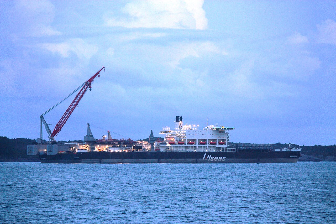
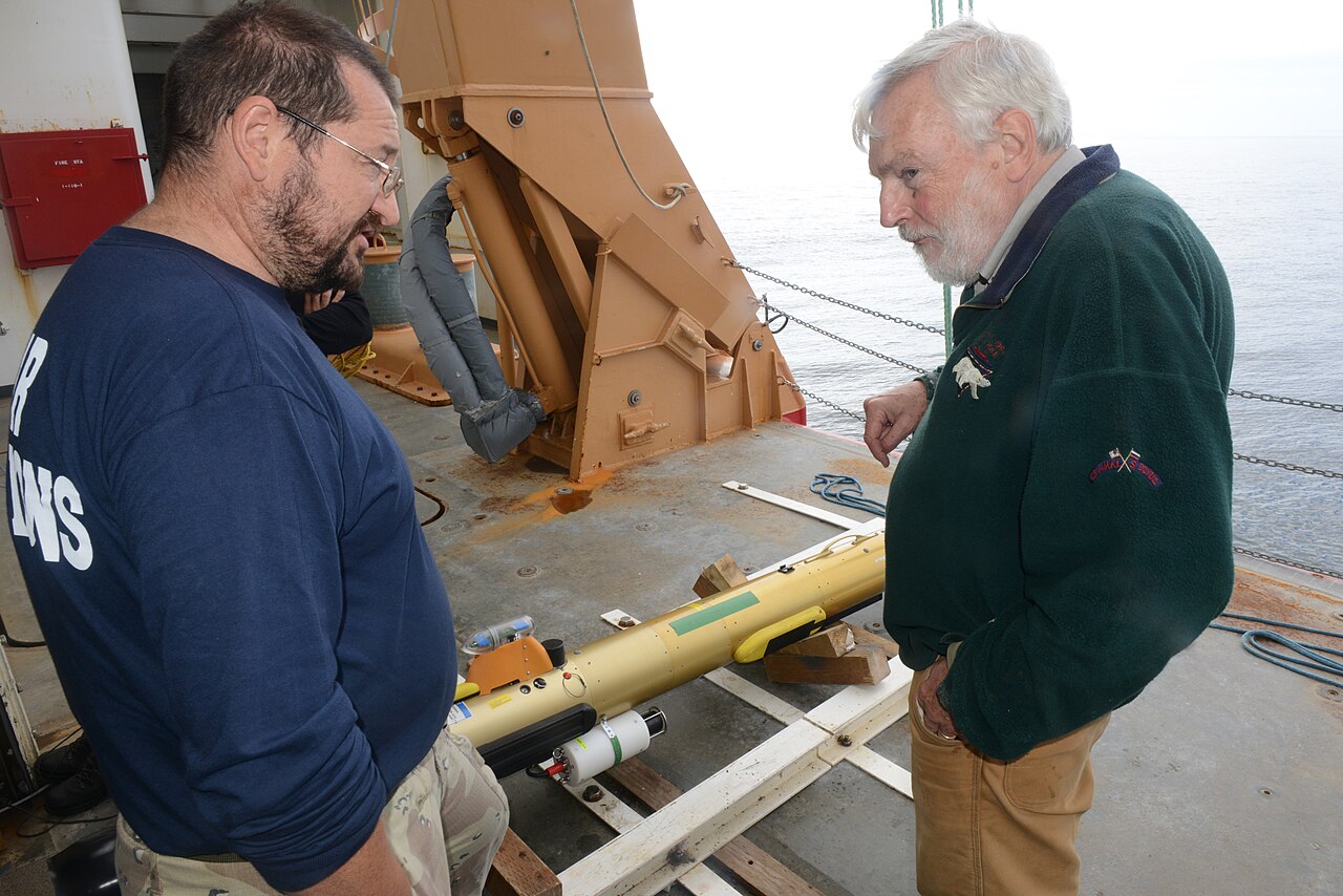
The vessels and the frames used in these exercises
The problems below are about three kinds of vehicle. Figure 4.6 shows two of them. Problems 1, 3 and 5 concern heavy-lift and installation work, where a vessel’s attitude has to be known to a fraction of a degree because a topside weighing tens of thousands of tonnes must be set down on a jacket without touching its legs. Problems 6, 7 and 8 concern a torpedo-shaped autonomous underwater vehicle, which has no vertical thruster at all: it changes depth by pitching its whole body and flying, which is why the coupling between its attitude and its velocity is the heart of those problems.
(a) A heavy-lift and installation vessel. Placing or removing a complete topside is a centimetre-and-fraction-of-a-degree operation, and every quantity in it is quoted relative to a frame that must be stated unambiguously — the subject of Problems 1, 3 and 5.
(b) A torpedo-shaped autonomous underwater vehicle on deck before launch. Its only actuators are a propeller on the body \(x\) axis and control surfaces that set the attitude, so depth is changed by pitching the hull — the situation of Problems 6, 7 and 8.
Figure 4.6: Two of the vehicle types used in the exercises of this chapter. Image credits: (a) Cavernia, CC0; (b) U.S. Coast Guard, Petty Officer 1st Class Shawn Eggert, public domain. Both are hosted on Wikimedia Commons.
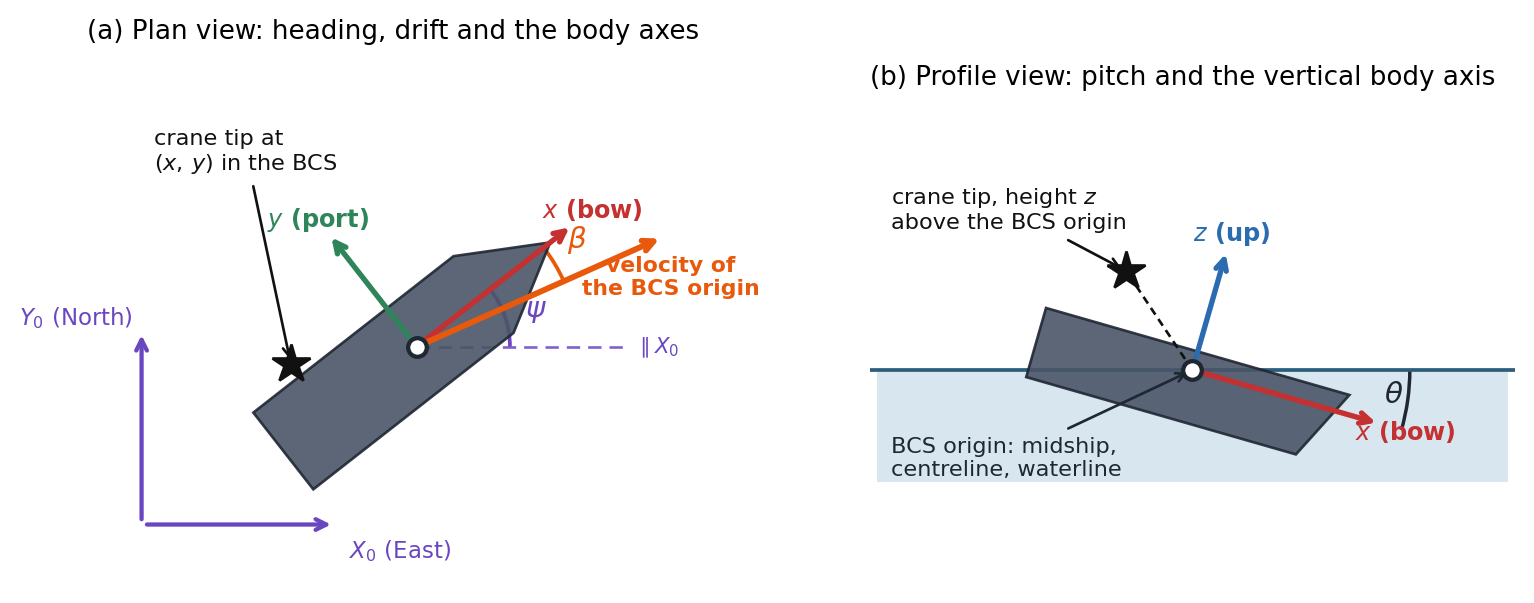
Figure 4.7 fixes the notation. Every angle, axis and offset used in the problems appears on it once, drawn in the book’s conventions: the GCS is East-North-Up, the body \(x\) axis runs along the bow, \(y\) to port and \(z\) up, and the BCS origin sits at midship on the centreline at the waterline. Note in particular that the heading \(\psi\) is measured at the BCS origin against a line parallel to \(X_0\), and that the velocity of the origin need not lie along the centreline — the angle between them is the drift angle used in Problems 6 and 10.
Figure 4.7: The frames, angles and offsets used throughout these exercises. (a) Plan view, looking down: the fixed GCS axes, the body axes carried by the vessel, the heading \(\psi\), and the drift angle \(\beta\) between the centreline and the velocity of the BCS origin. (b) Profile view: the pitch \(\theta\) and the body \(z\) axis. The star marks a point fixed in the vessel, such as the crane tip of Problem 2, whose body-frame coordinates are \((x, y, z)\). Angles are drawn larger than they would ever be in service.
Reading a platform’s orientation off a survey. During a jacket installation the orientation of a heavy-lift vessel is fixed by a survey that reports the directions of two of the vessel’s body axes, expressed in the GCS: \[\hat{i} = [0.8147,\ 0.5704,\ 0.1045]^T, \qquad \hat{j} = [-0.5788,\ 0.7888,\ 0.2068]^T\]
Starting from the definition \(\eqref{eq-rotm-def}\), show that the columns of \(\boldsymbol{R}\) are the BCS unit vectors \(\hat{i}\), \(\hat{j}\), \(\hat{k}\) expressed in the GCS, while the rows of \(\boldsymbol{R}\) are the GCS unit vectors \(\hat{i}_0\), \(\hat{j}_0\), \(\hat{k}_0\) expressed in the BCS. Which of these two statements makes \(\boldsymbol{R}^T\) the GCS \(\to\) BCS transformation?
Verify that the two reported vectors are of unit length and mutually orthogonal to within the quoted precision. Construct the missing third body axis and assemble \(\boldsymbol{R}\). Explain why the right handedness of the BCS is what forces your choice of sign, and state what a survey with \(\hat{k} = -\hat{i}\times\hat{j}\) would imply about the reported data.
By comparing your matrix with \(\eqref{eq-rotm-expansion}\), derive general expressions for \(\phi\), \(\theta\) and \(\psi\) in terms of the elements \(R_{ij}\), and evaluate them. Explain why the third row and first column are the natural places to look, and why a four-quadrant \(\operatorname{atan2}\) is needed for \(\phi\) and \(\psi\) but not for \(\theta\).
Show algebraically, using \(\eqref{eq-rotm-expansion}\), that the triple \((\phi + 180^\circ,\ 180^\circ - \theta,\ \psi + 180^\circ)\) produces exactly the same \(\boldsymbol{R}\) as \((\phi, \theta, \psi)\). Evaluate this second solution for the surveyed matrix, and explain how restricting \(\theta\) to \([-90^\circ, 90^\circ]\) removes the ambiguity. Which of the two solutions would a naive \(\theta = \arcsin(-R_{31})\) always return, and why?
A second survey crew mounts its reference frame with \(x\) pointing aft and \(y\) to starboard — that is, their BCS is the vessel’s BCS rotated by \(180^\circ\) about its own \(z\) axis. Show that their rotation matrix is \(\boldsymbol{R}\boldsymbol{R}_{z,180^\circ}\), prove that their Euler angles are exactly \((-\phi,\ -\theta,\ \psi - 180^\circ)\), and evaluate them. A colleague concludes that the vessel is now pitching and rolling the other way. Is anything physical different?
Where the crane tip actually goes. An FPSO carries a deck crane whose tip, when the boom is slewed out on the port quarter, sits at \[\vec{r} = [-45,\ 28,\ 30]^T \text{ m}\] in the BCS, the BCS origin being at the intersection of midship, centreline and the loaded waterline. At one instant the vessel’s pose is \(\{\eta_1\} = [120,\ -340,\ 1.2]^T\) m and \(\{\eta_2\} = (\phi, \theta, \psi) = (4^\circ,\ 2^\circ,\ 30^\circ)\).
Write down the GCS position of the crane tip in terms of \(\{\eta_1\}\), \(\boldsymbol{R}\) and \(\vec{r}\), justify it in one sentence, and evaluate it.
Show from \(\eqref{eq-rotm-expansion}\) that the vertical GCS coordinate of any point fixed in the vessel is independent of the heading \(\psi\), exactly and not merely to first order. Which structural feature of \(\boldsymbol{R}_{z,\psi}\) is responsible?
Expand \(\eqref{eq-rotm-expansion}\) to first order in the three angles to show that \[\boldsymbol{R} \approx \boldsymbol{I} + \boldsymbol{S}, \qquad \boldsymbol{S} = \begin{bmatrix} 0 & -\psi & \theta \\ \psi & 0 & -\phi \\ -\theta & \phi & 0\end{bmatrix}\] and hence that the displacement of a point \(\vec{r}\) relative to the BCS origin is \(\boldsymbol{S}\vec{r}\). Deduce that the vertical component is \(\delta z \approx \phi y - \theta x\), and note which coordinate of \(\vec{r}\) is absent from it.
The vessel oscillates with roll amplitude \(4^\circ\), pitch amplitude \(2^\circ\) and heave amplitude \(1.2\) m, all in phase. Compute the amplitude of the vertical motion of the crane tip from the approximation of part (c) and from the exact matrix, and compare both with the heave amplitude alone. By what factor is the motion at the tip amplified, and what is the error committed by linearizing?
Find the locus of points on the deck at which the first-order vertical motion vanishes for these amplitudes, and describe it geometrically. Explain why this “quiet line” rotates as the ratio of roll to pitch amplitude changes with sea state, and why that makes it useless as a permanent siting rule for motion-sensitive equipment.
Two conventions, one platform. A motion reference unit on a heavy-lift vessel reports \((\phi, \theta, \psi) = (8^\circ,\ 5^\circ,\ 40^\circ)\). The vendor’s manual defines these angles in the XYZ order, that is \(\boldsymbol{R}_{XYZ} = \boldsymbol{R}_{x,\phi}\boldsymbol{R}_{y,\theta}\boldsymbol{R}_{z,\psi}\), whereas the lift-analysis software assumes the ZYX order \(\eqref{eq-rotm-fomulation}\) of this chapter.
Compute both matrices. Extract the bow direction \(\hat{i}\) in the GCS from each, and find the angle between the two bow directions. Do the same for the mast direction \(\hat{k}\).
Determine the ZYX angles that describe the orientation the vendor actually intended, and hence state the roll, pitch and heading errors committed by feeding the vendor’s three numbers straight into the software.
The lift plan is rejected if the heading is wrong by more than \(1^\circ\). Would this error be caught by a heading check alone? Comment on why an error of this kind is easy to miss in practice.
Show that to first order in the angles every rotation order gives the same matrix \(\boldsymbol{I} + \boldsymbol{S}\) of Problem 2(c), so that the two conventions can only differ at second order. Verify this by repeating part (a) with all three angles divided by \(10\), and confirm that the angle between the two bow directions falls by roughly a factor of \(100\).
Show that if any two of the three angles are zero, all rotation orders agree exactly. Use this to explain why a convention error can lie dormant through an entire calm-water commissioning trial and only appear once the vessel is working in a seaway.
What a levelling sensor can and cannot see. A three-axis accelerometer is bolted to the deck of a moored platform, aligned with the BCS. The platform is at rest, so the only acceleration the instrument senses is that due to gravity, which in the GCS is \([0,\ 0,\ -g]^T\). The instrument reads \[\vec{a} = [0.8550,\ -1.2925,\ -9.6868]^T \text{ m/s}^2\]
Show that the reading must be \(\vec{a} = \boldsymbol{R}^T[0,\ 0,\ -g]^T\), and hence, using \(\eqref{eq-rotm-expansion}\), that \[\vec{a} = g\,[\sin\theta,\ -\sin\phi\cos\theta,\ -\cos\phi\cos\theta]^T\] Confirm that \(|\vec{a}| = g\) for every orientation, and say which property of \(\boldsymbol{R}\) guarantees it.
Invert these relations to obtain \(\theta\) and \(\phi\) from the reading, and evaluate them. Then show that \(\psi\)cannot be obtained from this measurement at any orientation, and explain the reason in terms of the order of the ZYX rotations and the direction of gravity.
Verify your answer by reconstructing \(\vec{a}\) from the recovered angles.
Differentiate the relation for \(\theta\) to show that \(\mathrm{d}\theta/\mathrm{d}a_x = 1/(g\cos\theta)\). A cheap accelerometer has a bias of \(0.02\) m/s\(^2\) on each channel. Compute the resulting pitch error at \(\theta = 0^\circ\), \(60^\circ\) and \(85^\circ\), and comment on the trend.
Show that at \(\theta = \pm 90^\circ\) the reading becomes \(\vec{a} = \pm g\,[1,\ 0,\ 0]^T\)whatever the value of \(\phi\), so that roll joins heading in being unmeasurable. Relate this to Section 4.4.1, and state what additional sensor a vessel must carry to determine the orientation completely.
Float-over: the relative orientation of two bodies. In a float-over installation a barge carries the topsides between the legs of a jacket and lowers them onto it. What matters for mating is not the attitude of either body in the GCS, but the attitude of the barge relative to the jacket. Just before mating, surveys give
The mating tolerance requires relative roll and relative pitch each below \(0.5^\circ\) and relative heading below \(1.0^\circ\).
Let \(\boldsymbol{R}_J\) and \(\boldsymbol{R}_B\) carry vectors from the jacket frame and the barge frame respectively into the GCS. Derive the matrix that carries a vector from the barge frame into the jacket frame, and verify from \(\eqref{eq-rotm-orthogonal}\) that it is itself a rotation matrix.
Evaluate this relative matrix and extract its ZYX Euler angles.
A junior engineer computes the relative attitude as the difference of the two sets of Euler angles. Evaluate that difference, compare it with the exact answer of part (b), and quantify the discrepancy in each channel.
Show that the difference rule is correct to first order but wrong at second order, and confirm the size of the discrepancy against the products of the angles involved. Express the largest discrepancy as a percentage of the tightest tolerance and comment on whether the shortcut is acceptable here.
The barge is to be re-ballasted to bring the relative pitch to zero without altering its heading or its roll. Determine the required \(\theta_B\), and state whether the naive answer \(\theta_B = \theta_J\) is adequate.
Speed over ground, drift and the climb of a trimmed vehicle. A survey vessel has body-frame velocity components \(u = 6.2\) m/s, \(v = -0.9\) m/s, \(w = 0.15\) m/s at an instant when its pose angles are \((\phi, \theta, \psi) = (-6^\circ,\ 1.5^\circ,\ 62^\circ)\).
Compute \(\{\dot{\eta}_1\}\) from \(\eqref{eq-kinematics-translation}\). Define the course over ground as \(\chi = \operatorname{atan2}(\dot{y}_0, \dot{x}_0)\) and evaluate it.
Show that when \(\phi = \theta = 0\) the course is exactly \(\chi = \psi + \operatorname{atan2}(v, u)\), so that the difference between course and heading is precisely the drift (sideslip) angle. Evaluate this idealized course for the given \(u\) and \(v\), and compare it with the exact value from part (a). How large is the error introduced by ignoring the \(6^\circ\) of heel?
Prove from \(\eqref{eq-rotm-orthogonal}\) that \(|\{\dot{\eta}_1\}| = |\{\nu_1\}|\) for every orientation, and verify numerically. Then compute the horizontal speed made good and explain why it is smaller.
Show from the third row of \(\eqref{eq-rotm-expansion}\) that \[\dot{z}_0 = -u\sin\theta + v\sin\phi\cos\theta + w\cos\phi\cos\theta\] and hence that a vehicle with no heave velocity in body axes still changes altitude whenever it is trimmed and moving ahead. Evaluate \(\dot{z}_0\) for the given data with \(w\) set to zero.
An AUV runs at \(2.0\) m/s along its own \(x\) axis with \(v = w = 0\) and no heel. Derive its rate of descent as a function of pitch and evaluate it at \(\theta = 10^\circ\) (bow down, by the sign convention noted at the head of these exercises). How long does it take to reach \(150\) m depth, and what horizontal distance does it cover doing so? Comment on why a vehicle that is nominally “swimming forwards” is in fact the standard way to change depth.
Euler rates are not an angular velocity. A survey AUV is flying a steady helical descent, holding a constant bank \(\phi = 15^\circ\) and a constant bow-down pitch \(\theta = 20^\circ\) while its heading changes at the constant rate \(\dot{\psi} = 0.05\) rad/s.
Compute the body-frame angular velocity \(\{\nu_2\} = [p, q, r]^T\) from \(\eqref{eq-ang-vel}\). All three components are non-zero even though only one Euler angle is changing — explain why in terms of the axis about which \(\dot{\psi}\) acts.
Show that \(r = \dot{\psi}\cos\phi\cos\theta\) whenever \(\dot{\phi} = \dot{\theta} = 0\), so a yaw-axis rate gyro always under-reads the turn rate of a banked or pitched vehicle. Evaluate the shortfall here, and compute the heading error accumulated if \(r\) is naively integrated as \(\dot{\psi}\) over a five-minute descent.
At a later instant, while the attitude is momentarily the same \((\phi, \theta) = (15^\circ,\ 20^\circ)\), the instruments record \(p = 0.030\), \(q = 0.012\), \(r = -0.045\) rad/s. Compute the Euler rates from \(\eqref{eq-kinematics-rotation}\).
For the rates of part (c) compute \(|\{\dot{\eta}_2\}|\) and \(|\{\nu_2\}|\) and show that they differ. Then show that for the single-rate case of part (a) they agree exactly, and explain what distinguishes the two situations.
The columns of \(\boldsymbol{J}_2^{-1}\) are the three unit vectors about which \(\dot{\phi}\), \(\dot{\theta}\) and \(\dot{\psi}\) act, expressed in the BCS. Write them down from \(\eqref{eq-ang-vel}\), verify that each is of unit length, and show that while the \(\dot{\phi}\) and \(\dot{\theta}\) axes are perpendicular, and the \(\dot{\theta}\) and \(\dot{\psi}\) axes are perpendicular, the angle between the \(\dot{\phi}\) and \(\dot{\psi}\) axes is \(90^\circ + \theta\). Evaluate it here. This non-orthogonality is the whole reason \(\{\eta_2\}\) is not a vector: explain why, and predict from the formula what happens at \(\theta = 90^\circ\).
Gimbal lock in a hovering AUV. A hover-capable inspection AUV is commanded to pitch nose-up through the vertical so as to inspect the underside of a platform deck. Its control software carries the orientation as ZYX Euler angles.
Verify \(\eqref{eq-rotm-gimbal-lock}\) by evaluating \(\boldsymbol{R}\) at \((\phi, \theta, \psi) = (35^\circ,\ 90^\circ,\ 20^\circ)\) and at \((50^\circ,\ 90^\circ,\ 35^\circ)\), and comment on the result. Give a third, quite different pair \((\phi, \psi)\) producing the same matrix.
With the body rates held at \([p, q, r] = [0.02,\ 0.05,\ 0.01]\) rad/s and \(\phi = 35^\circ\), tabulate the Euler rates from \(\eqref{eq-kinematics-rotation}\) at \(\theta = 60^\circ\), \(80^\circ\), \(88^\circ\), \(89.5^\circ\) and \(89.9^\circ\). Identify which rates diverge and confirm that they grow as \(1/\cos\theta\).
Compute \(|\{\nu_2\}|\) at each of those pitch angles. What does the contrast with part (b) tell you about where the difficulty actually lies?
Evaluate \(\boldsymbol{J}_2^{-1}\) at \(\theta = 90^\circ\) and find a non-zero \(\{\dot{\eta}_2\}\) for which \(\{\nu_2\} = 0\). Interpret this vector physically, and reconcile it with your answer to part (a).
Show that at \(\theta = 90^\circ\) the columns of \(\boldsymbol{J}_2^{-1}\) span only a two-dimensional space, and find the body-axis direction of angular velocity that no choice of Euler rates can produce. Is the AUV physically unable to rotate that way? State the practical remedy, and explain why a ZYX order is nevertheless the right choice for a conventional ship.
When may the kinematics be linearized? Almost the whole of seakeeping theory replaces \(\eqref{eq-kinematics-compact}\) by \(\{\dot{\eta}\} \approx \{\nu\}\). This problem establishes what that costs.
Using the first-order expansions of Problem 2(c), show that \(\boldsymbol{R} = \boldsymbol{I} + \boldsymbol{S} + O(2)\) and, from \(\eqref{eq-kinematics-rotation}\), that \[\boldsymbol{J}_2 = \boldsymbol{I} + \boldsymbol{T} + O(2), \qquad \boldsymbol{T} = \begin{bmatrix} 0 & 0 & \theta \\ 0 & 0 & -\phi \\ 0 & \phi & 0\end{bmatrix}\] Hence show that the corrections to \(\{\dot{\eta}\} = \{\nu\}\) are products of an angle with a velocity, and explain in what sense \(\{\dot{\eta}\} \approx \{\nu\}\) is therefore a statement about two independent small quantities and not one.
Define \(\varepsilon_R = \max_{ij}|R_{ij} - (\boldsymbol{I}+\boldsymbol{S})_{ij}|\) and \(\varepsilon_J\) analogously for \(\boldsymbol{J}_2\) and \(\boldsymbol{I}+\boldsymbol{T}\). Tabulate both for \(\phi = \theta = \psi = 1^\circ, 5^\circ, 10^\circ, 20^\circ\) and \(30^\circ\).
Confirm from the table that both errors are second order, and determine the angle at which each first exceeds \(1\%\).
A ship in a seaway rolls \(\pm5^\circ\) and pitches \(\pm2^\circ\). Using Problem 2, state the error in the predicted vertical motion of the crane tip and decide whether linearization is justified.
Repeat the judgement for a semi-submersible under tow rolling \(\pm15^\circ\) and for the AUV of Problem 7 at \(\theta = -20^\circ\). In each case say which of \(\boldsymbol{R}\) and \(\boldsymbol{J}_2\) degrades first, and explain the difference from the structure of \(\boldsymbol{T}\).
The turning circle. A ship of length \(L = 180\) m settles into a steady turn with constant body-frame velocities \(u = 5.5\) m/s, \(v = -0.8\) m/s, \(w = 0\) and a constant yaw rate. Take the heel and trim to be zero for parts (a)–(c).
With \(\phi = \theta = 0\), show that \(\eqref{eq-kinematics-rotation}\) gives \(\dot{\psi} = r\), and integrate \(\eqref{eq-kinematics-translation}\) analytically to obtain \(x_0(t)\) and \(y_0(t)\). Hence prove that the path is a circle and that its radius is \(R_{\text{turn}} = U/r\) with \(U = \sqrt{u^2+v^2}\). Locate its centre relative to the ship.
For \(r = 0.018\) rad/s evaluate \(U\), \(R_{\text{turn}}\), the steady turning diameter in ship lengths and the time to complete one revolution.
Compute the drift angle and show that the tangent to the path is not along the ship’s centreline. By how much does the bow point inside the turn, and what is the transverse speed of the stern relative to the water compared with that of the bow, given that the BCS origin is at midship?
Now let the ship carry a steady heel \(\phi = -6^\circ\) and trim \(\theta = 0.5^\circ\). Show that body rates \(p = q = 0\) with \(r = 0.018\) rad/s are not compatible with a steady heel: compute \(\dot{\phi}\) and \(\dot{\theta}\) from \(\eqref{eq-kinematics-rotation}\) and show they are non-zero. Then find the body rates \([p, q, r]\) that do hold \(\phi\) and \(\theta\) constant while turning at a heading rate \(\dot{\psi} = 0.018\) rad/s.
With those body rates, and still with \(w = 0\), compute \(\dot{z}_0\). The ship is clearly not climbing out of the water, so determine the body-frame heave velocity \(w\) that actually holds it at constant draft, and comment on what this says about interpreting \(w\) as “heave velocity”.
Answer Key
Problem 1 — Reading a platform’s orientation off a survey
(a) Read by columns, \(\boldsymbol{R}\) lists the body axes in global components; read by rows, it lists the global axes in body components.
Columns. The first column of \(\eqref{eq-rotm-def}\) is \([\hat i\cdot\hat i_0,\ \hat i\cdot\hat j_0,\ \hat i\cdot\hat k_0]^T\): exactly the GCS components of \(\hat i\). The same holds for the other two columns.
Rows. Read the other way, the rows of \(\eqref{eq-rotm-def}\) are the GCS unit vectors resolved in the BCS.
Which makes \(\boldsymbol{R}^T\) the GCS \(\to\) BCS map. The row statement: the columns of \(\boldsymbol{R}^T\) are \(\hat i_0\), \(\hat j_0\), \(\hat k_0\) in BCS components, so \(\boldsymbol{R}^T\) maps GCS components to BCS components, consistent with \(\boldsymbol{R}^{-1} = \boldsymbol{R}^T\).
(b) The third axis is fixed by right-handedness: \(\hat k = \hat i\times\hat j\).
Checks.\(|\hat i| = 1.000006\), \(|\hat j| = 0.999991\) and \(\hat i\cdot\hat j = -0.000006\), all correct to the quoted four decimals.
Third axis and matrix.\(\hat k = \hat i\times\hat j = [0.0355,\ -0.2290,\ 0.9728]^T\), so \[\boldsymbol{R} = \begin{bmatrix} 0.8147 & -0.5788 & 0.0355 \\ 0.5704 & 0.7888 & -0.2290 \\ 0.1045 & 0.2068 & 0.9728 \end{bmatrix}.\]
Why the sign. The BCS is defined to be right handed. With \(\hat k = -\hat i\times\hat j\) the frame would be left handed: its matrix would be a reflection, not a rotation, and would describe no physical reorientation. A survey reporting such a triad has recorded one axis with its sign reversed.
Data quality.\(\max|\boldsymbol{R}^T\boldsymbol{R} - \boldsymbol{I}| = 1.9e-05\): \(\eqref{eq-rotm-orthogonal}\) holds only to the quoted rounding, which is the residual a real survey leaves and a useful test of self-consistency.
(c) The angles are read from the third row and first column, the only places where they appear unmixed.
Where to look. From \(\eqref{eq-rotm-expansion}\) the third row is \([-s_2,\ s_1c_2,\ c_1c_2]\) and the first column is \([c_2c_3,\ c_2s_3,\ -s_2]^T\). Hence \[\begin{aligned} \theta &= \arcsin(-R_{31}), \\ \psi &= \operatorname{atan2}(R_{21}, R_{11}), \\ \phi &= \operatorname{atan2}(R_{32}, R_{33}). \end{aligned}\]
Values.\(\phi = 12.002^\circ\), \(\theta = -5.998^\circ\), \(\psi = 34.997^\circ\): round numbers to the precision the survey carries; the third-decimal departures are the four-figure rounding of part (b).
Why \(\operatorname{atan2}\) for \(\phi\) and \(\psi\) but not \(\theta\).\(\phi\) and \(\psi\) each come from a pair of elements sharing the positive factor \(c_2\), so the pair fixes the quadrant over the full \(360^\circ\). \(\theta\) comes from a single element and is confined to \([-90^\circ, 90^\circ]\) by convention, which is exactly the range of \(\arcsin\).
(d) Every orientation has two Euler triples; restricting \(\theta\) to \(\pm90^\circ\) picks one.
Why the second triple works. With \(\phi' = \phi + 180^\circ\), \(\theta' = 180^\circ - \theta\), \(\psi' = \psi + 180^\circ\): \(s_1' = -s_1\), \(c_1' = -c_1\), \(s_2' = s_2\), \(c_2' = -c_2\), \(s_3' = -s_3\), \(c_3' = -c_3\). Every entry of \(\eqref{eq-rotm-expansion}\) is a product of two primed factors whose sign changes cancel, for example \(R_{11}' = c_2'c_3' = (-c_2)(-c_3) = c_2c_3\) and \(R_{12}' = -c_1's_3' + s_1's_2'c_3' = -c_1s_3 + s_1s_2c_3\).
Second solution.\((-167.998^\circ,\ -174.002^\circ,\ -145.003^\circ)\), reproducing the matrix to \(1.1e-05\).
Removing the ambiguity. Its pitch lies outside \([-90^\circ, 90^\circ]\), so the convention selects the first solution. A naive \(\theta = \arcsin(-R_{31})\) can only return that branch: the ambiguity is resolved silently by the convention, not by the data.
(e) The second crew’s angles change sign, but nothing physical differs: they have resolved the same inclination on reversed axes.
Their matrix. Their axes are \(-\hat i\), \(-\hat j\), \(+\hat k\), so the columns are \([-\hat i, -\hat j, \hat k] = \boldsymbol{R}\boldsymbol{R}_{z,180^\circ}\) with \(\boldsymbol{R}_{z,180^\circ} = \operatorname{diag}(-1, -1, 1)\).
Their angles. Turning an axis through \(180^\circ\) about \(z\) reverses it, so \(\boldsymbol{R}_{z,180^\circ}\boldsymbol{R}_{y,-\theta}\boldsymbol{R}_{z,180^\circ}^T = \boldsymbol{R}_{y,\theta}\), and likewise about \(x\). Therefore \[\boldsymbol{R}_{z,\psi - 180^\circ}\boldsymbol{R}_{y,-\theta}\boldsymbol{R}_{x,-\phi} = \boldsymbol{R}_{z,\psi}\boldsymbol{R}_{y,\theta}\boldsymbol{R}_{x,\phi}\boldsymbol{R}_{z,180^\circ}.\]
Takeaway. An orientation is meaningless until the frame it refers to is stated (figure below).
Problem 1, computed. The surveyed body axes projected on the horizontal and on a vertical plane (solid), and the second crew’s axes (dashed): \(\hat i\) and \(\hat j\) reversed, \(\hat k\) shared. The vessel is the same; only the axes used to describe it differ, which is why their roll and pitch change sign.
Problem 2 — Where the crane tip actually goes
(a) Rotate the body-frame offset into the GCS, then add the position of the BCS origin.
Formula.\(\vec r_{0,\text{tip}} = \{\eta_1\} + \boldsymbol{R}\vec r\): \(\vec r\) is given in BCS components, and \(\eqref{eq-rotm-bcs-to-gcs}\) brings it into GCS components before the two vectors can be added.
Values.\(\boldsymbol{R}\vec r = [-50.903,\ 0.447,\ 33.431]^T\) m and \(\vec r_{0,\text{tip}} = [69.097,\ -339.553,\ 34.631]^T\) m.
(b) Yawing about the vertical cannot change any height.
Algebra. The third row of \(\eqref{eq-rotm-expansion}\) is \([-s_2,\ s_1c_2,\ c_1c_2]\), with no \(\psi\) in it, so every point of the vessel has \[z_0 = z_{0,\text{BCS origin}} - x\sin\theta + y\sin\phi\cos\theta + z\cos\phi\cos\theta.\]
Cause.\(\boldsymbol{R}_{z,\psi}\) has third row \([0,\ 0,\ 1]\), so the bottom row of \(\boldsymbol{R}_{z,\psi}\boldsymbol{R}_{y,\theta}\boldsymbol{R}_{x,\phi}\) is just the bottom row of \(\boldsymbol{R}_{y,\theta}\boldsymbol{R}_{x,\phi}\).
(c) To first order, a point’s vertical motion depends only on where it sits in the waterplane, not on its height.
Expansion. Put \(s_i \approx\) angle, \(c_i \approx 1\) and drop products of angles. For example \(R_{12} = -c_1s_3 + s_1s_2c_3 \approx -\psi\) and \(R_{13} = s_1s_3 + c_1s_2c_3 \approx \theta\), giving \(\boldsymbol{R} \approx \boldsymbol{I} + \boldsymbol{S}\) with \(\boldsymbol{S}\) skew-symmetric as quoted.
Displacement.\[\boldsymbol{R}\vec r - \vec r \approx \boldsymbol{S}\vec r = [\theta z - \psi y,\ \psi x - \phi z,\ \phi y - \theta x]^T,\]\[\delta z \approx \phi y - \theta x.\]
Absent coordinate. The height \(z\): roll acts on the transverse lever arm and pitch on the longitudinal one, and height matters only for the horizontal components.
(d) Most of the crane tip’s vertical motion comes from rotation, not heave.
First order.\(\delta z = \phi y - \theta x = (0.06981)(28) - (0.03491)(-45) = 3.5256\) m; with heave in phase the tip amplitude is \(1.2 + 3.5256 = 4.7256\) m.
Exact.\(\delta z = -x\sin\theta + y\sin\phi\cos\theta + z(\cos\phi\cos\theta - 1) = 3.4312\) m, so \(4.6312\) m.
Amplification. The tip moves \(3.86\) times as far as the BCS origin: \(74\%\) of its motion is rotation, which is why crane operability is quoted at the tip.
Linearisation error.\(0.0944\) m, \(2.75\%\) of the rotational part and only \(2.04\%\) of the total: acceptable at these angles.
(e) There is a quiet line on the deck, but it turns with the sea state.
Locus.\(\phi y - \theta x = 0\) gives \(y = (\theta/\phi)x = 0.500\,x\): a straight line through the BCS origin at \(\arctan(\theta/\phi) = 26.57^\circ\) to the centreline. The vertical motion grows linearly with distance from it.
Why it moves. Its direction depends only on the ratio of roll to pitch amplitude, a property of the sea state and heading, not of the ship. In beam seas roll dominates and the line swings towards the centreline; in head seas pitch dominates and it swings towards the transverse.
Siting rule. Useless as a permanent rule. The robust conclusion is the weaker one: points near midship on the centreline are quiet for all ratios (figure below).
Problem 2(c)–(e), computed.(a) First-order vertical motion due to \(4^\circ\) of roll and \(2^\circ\) of pitch in phase, over the deck of a \(280 \times 56\) m hull (contours in metres). It vanishes along the red quiet line and grows with distance from it; the crane tip on the port quarter is far from it. (b) As the ratio of pitch to roll changes with heading and sea state, the quiet line swings about midship.
Problem 3 — Two conventions, one platform
(a) The same three numbers applied in a different order describe a different attitude.
(c) A heading check alone passes the plan: convention errors hide in roll and pitch.
Heading. Wrong by only \(0.241^\circ\), inside the \(1^\circ\) gate, while roll and pitch are wrong by \(1.33^\circ\) and \(6.34^\circ\).
Why it is easy to miss. Yaw is the first rotation in ZYX and the last in XYZ, and in both it is the one least disturbed by the other two when they are small. The channel an operator naturally checks against a compass looks right, while the channels a lift plan depends on are wrong.
(d) All rotation orders agree to first order and differ only at second order.
Argument. Each elemental matrix is \(\boldsymbol{I} + \boldsymbol{S}_a\) to first order, and \((\boldsymbol{I} + \boldsymbol{S}_a)(\boldsymbol{I} + \boldsymbol{S}_b) = \boldsymbol{I} + \boldsymbol{S}_a + \boldsymbol{S}_b + \boldsymbol{S}_a\boldsymbol{S}_b\). Matrix addition commutes, so every order shares the first-order part \(\boldsymbol{I} + \boldsymbol{S}\); they differ only through the products, which are second order.
Check. Dividing all three angles by \(10\) reduces the bow separation from \(6.342^\circ\) to \(0.05746^\circ\), a factor of \(110.4\): the factor of \(100\) of a second-order quantity (figure below).
Problem 3(d), computed. The disagreement between the two rotation orders as the attitude is scaled up from almost nothing. It follows a slope of two on log axes: ten times smaller angles give a hundred times smaller error, so the mistake is invisible in calm water.
(e) With only one angle non-zero there is no order to get wrong, so a convention error stays hidden until the vessel rolls and pitches together.
Proof. If two angles vanish, only one elemental matrix differs from \(\boldsymbol{I}\), and a single matrix has no ordering.
Consequence. A vessel upright at the quay has only a heading, so all twelve conventions agree and a commissioning trial shows perfect agreement. The error appears only in a seaway, once roll and pitch are both non-zero, when it is likely to be blamed on the sea rather than on the interface.
Problem 4 — What a levelling sensor can and cannot see
(a) The sensor resolves gravity onto the body axes, so it reads the third row of \(\boldsymbol{R}\).
Reading. The instrument applies the GCS \(\to\) BCS map \(\boldsymbol{R}^T\). Since \((\boldsymbol{R}^T\vec v)_i = \sum_jR_{ji}v_j\), the vector \([0, 0, -g]^T\) picks out the third row: \[\vec a = -g[R_{31},\ R_{32},\ R_{33}]^T = -g[-s_2,\ s_1c_2,\ c_1c_2]^T.\]
Magnitude.\(g\sqrt{s_2^2 + c_2^2(s_1^2 + c_1^2)} = g\). In general \(|\boldsymbol{R}^T\vec v|^2 = \vec v^T\boldsymbol{R}\boldsymbol{R}^T\vec v = |\vec v|^2\) by \(\eqref{eq-rotm-orthogonal}\): a rotation cannot change the length of a vector.
(b) Gravity gives roll and pitch, but never heading.
Angles.\(\theta = \arcsin(a_x/g) = 5.000^\circ\) and \(\phi = \operatorname{atan2}(-a_y,\ -a_z) = 7.600^\circ\). The ratio \(a_y/a_z = \tan\phi\) alone would leave the quadrant undecided.
Why not \(\psi\). In ZYX, \(\psi\) is the first rotation, about \(Z_3 \parallel Z_0\): the direction gravity points along. Rotating about the direction of gravity leaves its body components unchanged. Formally, \(\psi\) appears only in the first two rows of \(\boldsymbol{R}\), and this measurement reads the third.
(c) The recovered angles reproduce the reading.
Check.\(\vec a = [0.8550,\ -1.2925,\ -9.6868]^T\) m/s\(^2\), matching to \(2.2e-05\) m/s\(^2\).
(d) A levelling sensor is most trustworthy when it has least to report.
Trend. The error grows as \(\sec\theta\): \(11.5\) times worse at \(85^\circ\) than upright. Near \(90^\circ\) the sine is flat, a large change in angle barely changes the reading, and the inversion is ill conditioned.
(e) At \(90^\circ\) of pitch the sensor loses roll as well: gimbal lock is a real loss of observability, not only an algebraic curiosity.
Reading at \(90^\circ\).\(c_2 = 0\) and \(s_2 = 1\), so \(\vec a = g[1,\ 0,\ 0]^T\) whatever \(\phi\) is: the \(\phi\)-dependence sat entirely in the vanished factor \(c_2\).
Link to Section 4.4.1. This is the degeneracy of \(\eqref{eq-rotm-gimbal-lock}\), where \(\boldsymbol{R}\) depends only on \(\phi - \psi\).
Remedy. A second, non-parallel reference direction: a gyrocompass, a magnetic heading reference or a dual-antenna GNSS baseline, all supplying a horizontal direction to complement gravity (figure below).
Problem 4, computed.(a) The body-frame components of gravity. As \(\theta \to 90^\circ\) the \(a_y\) and \(a_z\) curves for every roll angle collapse onto zero, so roll becomes unmeasurable, just as heading always is. (b) A fixed sensor bias produces a pitch error that grows as \(\sec\theta\).
Problem 5 — Float-over: the relative orientation of two bodies
(a) Go from the barge frame to the GCS, then back from the GCS into the jacket frame.
Derivation. A point of the barge has \(\vec p_0 = \boldsymbol{R}_B\vec p_B\) and \(\vec p_0 = \boldsymbol{R}_J\vec p_J\). Eliminating \(\vec p_0\) with \(\boldsymbol{R}_J^{-1} = \boldsymbol{R}_J^T\): \[\vec p_J = \boldsymbol{R}_J^T\boldsymbol{R}_B\,\vec p_B,\]\[\boldsymbol{R}_{J\leftarrow B} = \boldsymbol{R}_J^T\boldsymbol{R}_B.\]
It is a rotation.\((\boldsymbol{R}_J^T\boldsymbol{R}_B)^T(\boldsymbol{R}_J^T\boldsymbol{R}_B) = \boldsymbol{R}_B^T\boldsymbol{R}_J\boldsymbol{R}_J^T\boldsymbol{R}_B = \boldsymbol{I}\). The order matters: reversing the product answers a different question.
(b) The barge fails the mating tolerance on all three counts.
Check. roll \(1.881^\circ\) against \(0.5^\circ\) (fail), pitch \(2.170^\circ\) against \(0.5^\circ\) (fail), heading \(2.824^\circ\) against \(1.0^\circ\) (fail). The barge must be re-ballasted and re-headed before mating.
(c) Subtracting Euler angles is close to the exact answer, but not equal to it.
Naive difference.\((1.900^\circ,\ -2.200^\circ,\ 2.800^\circ)\), against the exact \((1.881^\circ,\ -2.170^\circ,\ 2.824^\circ)\).
Discrepancies in roll, pitch and heading: \(\Delta = +0.0193^\circ\), \(\Delta = -0.0299^\circ\), \(\Delta = -0.0235^\circ\).
(d) The difference rule is exactly the first-order result; its error is the discarded second-order product.
First order. With \(\boldsymbol{R} = \boldsymbol{I} + \boldsymbol{S}(\eta_2) + O(2)\) (Problem 2(c)), \[\begin{aligned} \boldsymbol{R}_J^T\boldsymbol{R}_B &= (\boldsymbol{I} - \boldsymbol{S}_J)(\boldsymbol{I} + \boldsymbol{S}_B) + O(2) \\ &= \boldsymbol{I} + (\boldsymbol{S}_B - \boldsymbol{S}_J) + O(2), \end{aligned}\] and \(\boldsymbol{S}_B - \boldsymbol{S}_J = \boldsymbol{S}(\eta_{2B} - \eta_{2J})\) because \(\boldsymbol{S}\) is linear in the angles. The error comes from the discarded \(-\boldsymbol{S}_J\boldsymbol{S}_B\).
Check. Halving all six angles reduces the largest discrepancy from \(0.0299^\circ\) to \(0.0074^\circ\), a factor of \(4.04\): the factor of four of a quadratic.
Acceptable? The discrepancy is \(6.0\%\) of the \(0.5^\circ\) tolerance, a noticeable slice of the error budget spent for no reason when the exact calculation is one matrix product. Not acceptable here; fine for a coarse check with a tolerance of several degrees (figure below).
Problem 5(d), computed. The error of subtracting Euler angles, as the two attitudes are scaled up or down together. It is second order: harmless for small attitudes, a growing share of the tolerance for larger ones.
(e) Matching the pitch angles does not quite null the relative pitch, because roll and heading differences leak into it at second order.
Required pitch. Solving \(\theta_{\text{rel}}(\theta_B) = 0\) with \(\phi_B\), \(\psi_B\) fixed gives \(\theta_B = 0.3702^\circ\), against the naive \(\theta_B = \theta_J = 0.4000^\circ\): \(0.0298^\circ\) apart.
Naive answer.\(\theta_B = \theta_J\) leaves a relative pitch of \(0.0298^\circ\), \(6.0\%\) of the tolerance: just inside the gate. It survives at these small angles, but would not at the larger attitudes of a lively sea.
Problem 6 — Speed over ground, drift and the climb of a trimmed vehicle
(a) The global velocity is the body velocity rotated into the GCS.
Values.\(\{\dot\eta_1\} = \boldsymbol{R}\{\nu_1\} = [3.6892,\ 5.0652,\ 0.0809]^T\) m/s; course over ground \(\chi = 53.933^\circ\) against a heading of \(62^\circ\).
(b) On an even keel, course minus heading is exactly the drift angle.
Derivation. With \(\phi = \theta = 0\), \(\boldsymbol{R} = \boldsymbol{R}_{z,\psi}\): \(\dot x_0 = u\cos\psi - v\sin\psi\), \(\dot y_0 = u\sin\psi + v\cos\psi\). With \(u = U\cos\beta\), \(v = U\sin\beta\) these are \(U\cos(\psi + \beta)\) and \(U\sin(\psi + \beta)\), so \(\chi = \psi + \beta\).
Values.\(\beta = -8.259^\circ\); idealised course \(53.741^\circ\) against the exact \(53.933^\circ\), an error of \(0.1921^\circ\).
Effect of heel.\(6^\circ\) of heel tilts the body \(xy\) plane, so part of \(w\) leaks into the horizontal and part of the sway leaves it: small, but growing with \(w\).
(c) Speed does not depend on the frame it is resolved in.
Proof.\(|\{\dot\eta_1\}|^2 = \{\nu_1\}^T\boldsymbol{R}^T\boldsymbol{R}\{\nu_1\} = \{\nu_1\}^T\{\nu_1\}\) by \(\eqref{eq-rotm-orthogonal}\); numerically both are \(6.266777\) m/s.
Horizontal speed made good.\(\sqrt{\dot x_0^2 + \dot y_0^2} = 6.2663\) m/s, smaller because the vertical component \(\dot z_0 = 0.0809\) m/s contributes nothing to progress across the chart.
(d) Body-frame heave velocity and rate of change of altitude are different quantities.
Derivation. The third row \([-s_2,\ s_1c_2,\ c_1c_2]\) of \(\eqref{eq-rotm-expansion}\) applied to \([u, v, w]^T\) gives the stated result.
With \(w = 0\).\(\dot z_0 = -0.0683\) m/s, against \(0.0809\) m/s with the actual \(w\). A vehicle held at \(w = 0\) is not thereby held at constant depth.
(e) A torpedo-shaped AUV changes depth by pitching its whole body and flying down.
Rate of descent. With \(v = w = 0\) and \(\phi = 0\), \(\dot z_0 = -U\sin\theta\), so a bow-down pitch (\(\theta > 0\)) descends: \(\dot z_0 = -0.3473\) m/s at \(\theta = 10^\circ\).
To \(150\) m.\(t = 431.9\) s \(= 7.2\) min, covering \(U\cos\theta\,t = 851\) m horizontally, nearly \(0.85\) km.
Why this is the standard way. The AUV has only a propeller on the \(x\) axis and control surfaces that set \(\theta\), so the transit needed to change depth is a real constraint on survey planning (figure below).
Problem 6(e), computed. Descent to \(150\) m at \(2\) m/s for several bow-down pitch angles; the ticks mark each minute. Steeper pitch shortens the transit, but even at \(20^\circ\) the AUV travels about \(400\) m to reach depth.
Problem 7 — Euler rates are not an angular velocity
(a) A turn about the global vertical has components on all three axes of a banked, pitched body.
Why all three.\(\dot\psi\) acts about \(Z_3 \parallel Z_0\), and no body axis of a banked, pitched vehicle is vertical. The components are the third column of \(\boldsymbol{J}_2^{-1}\): \(\hat k_0\) resolved in the BCS.
(b) A yaw-rate gyro under-reads the turn rate of a banked or pitched vehicle, and integrating it as a heading rate is a pure bookkeeping error.
Shortfall.\(r = \dot\psi c_1c_2 = 0.045384\) rad/s against \(\dot\psi = 0.05\) rad/s: \(9.23\%\) low, and since \(c_1c_2 \le 1\) it can never over-read.
Heading error over five minutes.\(\Delta\psi = (\dot\psi - r)T = 1.3849\) rad \(= 79.3^\circ\), against a true heading change of \(859^\circ\): enough to put the vehicle on the wrong survey line, with a perfect gyro.
(c) Euler rates follow from body rates through \(\boldsymbol{J}_2\).
(d) With more than one Euler rate the rates are summed about non-perpendicular axes, so their magnitude means nothing.
Part (c).\(|\{\dot\eta_2\}| = 0.051178\) but \(|\{\nu_2\}| = 0.055399\) rad/s, \(7.6\%\) apart.
Part (a). Both are \(0.050000\) rad/s. With a single non-zero rate, \(\{\dot\eta_2\}\) is one rotation about one axis, written in a different basis, and the column of \(\boldsymbol{J}_2^{-1}\) that carries it is a unit vector.
(e) The roll and yaw axes are not perpendicular, which is why \((\phi, \theta, \psi)\) is a set of coordinates and not a vector.
The three axes.\(\hat e_\phi = [1, 0, 0]^T\), \(\hat e_\theta = [0,\ c_1,\ -s_1]^T\), \(\hat e_\psi = [-s_2,\ s_1c_2,\ c_1c_2]^T\), each of unit length.
Their angles.\(\hat e_\phi\cdot\hat e_\theta = 0\) and \(\hat e_\theta\cdot\hat e_\psi = c_1s_1c_2 - s_1c_1c_2 = 0\), but \[\hat e_\phi\cdot\hat e_\psi = -\sin\theta,\]\[\angle(\hat e_\phi, \hat e_\psi) = \arccos(-\sin\theta) = 90^\circ + \theta.\] Here \(110.0^\circ\).
Consequence. With non-perpendicular axes that also move as \(\theta\) changes, the triple cannot be added, resolved or differentiated componentwise. At \(\theta = 90^\circ\) the angle is \(180^\circ\): roll and yaw axes are anti-parallel and one direction is lost (gimbal lock, Section 4.4.1) (figure below).
Problem 7, computed.(a) Five minutes of the helical descent: integrating the yaw gyro as if it were the heading rate falls behind by the shaded error. (b) The angle between the axes about which \(\dot\phi\) and \(\dot\psi\) act is \(90^\circ + \theta\); it reaches \(180^\circ\) at gimbal lock.
Problem 8 — Gimbal lock in a hovering AUV
(a) At \(90^\circ\) of pitch only \(\phi - \psi\) matters: a whole family of Euler triples describes one attitude.
Both triples.\[\boldsymbol{R} = \begin{bmatrix} 0.0000 & 0.2588 & 0.9659 \\ 0.0000 & 0.9659 & -0.2588 \\ -1.0000 & 0.0000 & 0.0000 \end{bmatrix},\] identical to \(5.6e-16\). Both have \(\phi - \psi = 15^\circ\), and by \(\eqref{eq-rotm-gimbal-lock}\) nothing else matters.
A third pair.\((\phi, \psi) = (-5^\circ, -20^\circ)\) gives the same matrix (difference \(2.8e-16\)). The map from angles to orientation is no longer invertible.
(b) Roll and yaw rates diverge as \(1/\cos\theta\); the pitch rate stays fixed.
Table of \(\{\dot\eta_2\} = \boldsymbol{J}_2\{\nu_2\}\):
\(\theta\) (deg)
\(\dot\phi\) (rad/s)
\(\dot\theta\) (rad/s)
\(\dot\psi\) (rad/s)
\(1/\cos\theta\)
60.0
0.0839
0.0352
0.0737
2.0
80.0
0.2291
0.0352
0.2123
5.8
88.0
1.0758
0.0352
1.0565
28.7
89.5
4.2449
0.0352
4.2251
114.6
89.9
21.1451
0.0352
21.1252
573.0
Pattern.\(\dot\theta = c_1q - s_1r\) has no \(c_2\) and stays at \(0.0352\) rad/s. \(\dot\phi\) and \(\dot\psi\) carry \(1/c_2\): from \(60^\circ\) to \(89.9^\circ\) the secant, and both rates, grow by a factor of \(286\).
(c) The vehicle turns perfectly steadily while its Euler rates run away: the difficulty is in the description, not the motion.
Value.\(|\{\nu_2\}| = 0.054772\) rad/s at every pitch angle.
Consequence. A numerical integration of \(\eqref{eq-kinematics-rotation}\) loses accuracy and then fails, while nothing whatever is happening to the AUV (figure below).
Problem 8(b)–(c), computed. Euler rates needed to describe a steady rotation as the pitch approaches \(90^\circ\) (log scale). Roll and yaw rates diverge as \(1/\cos\theta\); the vehicle’s actual rotation rate (dashed) does not change.
(d) At \(90^\circ\), rolling and yawing at equal rates produces no rotation at all.
Link to (a). Changing \(\phi\) and \(\psi\) together keeps \(\phi - \psi\), hence \(\boldsymbol{R}\), constant. The degenerate matrix and the singular \(\boldsymbol{J}_2\) are two views of one fact.
(e) The Euler-angle representation, not the vehicle, runs out of freedom.
Span. The columns are \([1, 0, 0]^T\), \([0,\ c_1,\ -s_1]^T\) and \([-1, 0, 0]^T\); the third is minus the first, so they span only a plane.
Unreachable direction.\(\hat n = [0,\ \sin\phi,\ \cos\phi]^T = [-0.0000,\ 0.5736,\ 0.8192]^T\): no Euler rates can produce an angular velocity along it. The AUV can of course rotate that way.
Remedy. Carry the attitude in a representation without a singularity (most simply the rotation matrix itself) and convert to Euler angles only for display.
Why ZYX suits a ship. Its singularity is at \(\theta = \pm90^\circ\), a pitch a ship never reaches. Hovering AUVs, cranes luffing to the vertical and aircraft are the vehicles forced away from Euler angles.
Problem 9 — When may the kinematics be linearized?
(a) Every correction to \(\{\dot\eta\} = \{\nu\}\) is an angle times a velocity, so the approximation needs small angles and small speeds.
\(\boldsymbol{R}\).\(\boldsymbol{I} + \boldsymbol{S} + O(2)\) from Problem 2(c).
\(\boldsymbol{J}_2\). With \(s_1 \approx \phi\), \(s_2 \approx \theta\), \(c_1, c_2 \approx 1\) in \(\eqref{eq-kinematics-rotation}\): \(s_1s_2/c_2 \approx \phi\theta\) is second order and drops, while \(c_1s_2/c_2 \approx \theta\) and \(s_1/c_2 \approx \phi\) survive, giving \(\boldsymbol{I} + \boldsymbol{T}\).
Corrections.\(\{\dot\eta_1\} = \{\nu_1\} + \boldsymbol{S}\{\nu_1\} + \cdots\) and \(\{\dot\eta_2\} = \{\nu_2\} + \boldsymbol{T}\{\nu_2\} + \cdots\). The error is first order in angle and first order in speed: second order in the combined smallness of the motion. Linear seakeeping is a small-amplitude theory, not merely a small-angle one, and \(5^\circ\) of roll matters more at high speed than at low.
(b) Both linearisation errors grow quickly with the angles.
All three angles equal:
angle (deg)
\(\varepsilon_R\)
\(\varepsilon_J\)
1
0.00031
0.00030
5
0.00801
0.00763
10
0.03322
0.03062
20
0.13760
0.12449
30
0.30709
0.28868
(c) Doubling the angle quadruples both errors, and \(\boldsymbol{R}\) crosses \(1\%\) first.
Second order.\(5^\circ \to 10^\circ\) multiplies \(\varepsilon_R\) by \(4.15\) and \(\varepsilon_J\) by \(4.02\); \(10^\circ \to 20^\circ\) by \(4.14\) and \(4.07\).
\(1\%\) thresholds.\(\varepsilon_R\) between \(5^\circ\) and \(10^\circ\); \(\varepsilon_J\) between \(10^\circ\) and \(20^\circ\) (figure below).
Problem 9, computed. Errors of the linearised \(\boldsymbol{R}\) and \(\boldsymbol{J}_2\) (log axes). All rise with slope two at small angles (second order). For pitch alone (dashed) the two start together, but \(\boldsymbol{R}\) levels off while \(\boldsymbol{J}_2\), which contains \(1/\cos\theta\), runs away towards the singularity at \(90^\circ\).
(d) For a ship in an operational seaway the linearisation error is negligible.
Crane tip (\(\phi = 5^\circ\), \(\theta = 2^\circ\)): \(4.0143\) m linear against \(3.8770\) m exact, an error of \(3.54\%\).
Judgement. The sea state itself is rarely known to better than \(10\)–\(20\%\), so linearisation is fully justified, and with it the superposition approach of Chapter 3.
(e)\(\boldsymbol{R}\) degrades gently with any large angle; \(\boldsymbol{J}_2\) degrades with pitch alone, and without bound.
Semi-submersible, \(15^\circ\) of roll.\(0.0341\) in \(\boldsymbol{R}\) and \(0.0341\) in \(\boldsymbol{J}_2\), about \(3.4\%\) and identical (both from \(1 - \cos\phi\)): the quadratic terms should be kept beyond a first estimate.
AUV, \(\theta = 20^\circ\).\(0.0603\) in \(\boldsymbol{R}\) against \(0.0642\) in \(\boldsymbol{J}_2\): here \(\boldsymbol{J}_2\) is worse.
Why.\(\boldsymbol{R}\) holds bounded products of sines and cosines, so its discarded terms are \(1 - \cos \approx \alpha^2/2\) whichever angle is involved. \(\boldsymbol{J}_2\) holds \(1/\cos\theta\), whose error \(\sec\theta - 1 \approx \theta^2/2\) is the same size at small \(\theta\) but unbounded: it runs away as \(\theta \to 90^\circ\) (Problem 8).
Problem 10 — The turning circle
(a) Constant body velocities and a constant yaw rate trace a circle, whose centre is a point fixed in the ship.
Heading. With \(\phi = \theta = 0\), \(\boldsymbol{J}_2 = \boldsymbol{I}\), so \(\dot\psi = r\) and \(\psi = \psi_0 + rt\).
Centre. Resolving the vector to the centre on the body axes with \(\boldsymbol{R}_{z,\psi}^T\), all \(\psi\)-dependence cancels: the centre is fixed in the BCS at \([-v/r,\ u/r,\ 0]^T = [44.4,\ 305.6,\ 0.0]^T\) m, \(306\) m abeam to port and \(44\) m forward of midship (the forward offset due entirely to the sway).
(b) The turn is about three ship lengths across.
Values.\(U = 5.5579\) m/s, \(R_{\text{turn}} = U/r = 308.8\) m, turning diameter \(2R_{\text{turn}} = 618\) m \(= 3.43L\); one revolution takes \(2\pi/r = 349\) s \(= 5.8\) min.
Context. A few ship lengths is typical; the IMO manoeuvring standard caps the tactical diameter at \(5L\).
(c) The ship crabs through the turn with its bow inside the circle, and its two ends move sideways in opposite directions.
Drift.\(\beta = \operatorname{atan2}(v, u) = -8.276^\circ\); the course is \(\psi + \beta\) (Problem 6(b)), so the bow points \(8.28^\circ\) inside the path. That angle of attack generates the side force that curves the path.
Bow and stern. The transverse velocity at \(x\) is \(v + rx\): \(+0.820\) m/s at the bow (\(x = +90\) m) and \(-2.420\) m/s at the stern (\(x = -90\) m). The stern swings outward, which is why a ship turning alongside a berth needs room astern (figure below).
Problem 10(a)–(c), computed. The steady turn drawn to scale, with the ship every \(45^\circ\) of heading. The hull always points slightly inside the circle (the drift angle); the bow’s velocity is turned slightly inward, the stern’s strongly outward: the stern swings out.
(d) Holding \(p = q = 0\) does not hold a steady heel: a steady heeled turn needs small roll and pitch rates.
With \(p = q = 0\).\(\dot\phi = c_1s_2r/c_2 = 0.000156\) rad/s and \(\dot\theta = -s_1r = 0.001882\) rad/s, neither zero (with \(\dot\psi = 0.017902\) rad/s): the attitude would drift.
Rates that hold \(\phi\) and \(\theta\). From \(\eqref{eq-ang-vel}\) with \(\{\dot\eta_2\} = [0, 0, 0.018]^T\): \[[p,\ q,\ r] = [-0.000157,\ -0.001881,\ 0.017901]^T\ \text{rad/s}.\]\(r = 0.017901 \ne \dot\psi\) (the under-read of Problem 7(b)), and a small pitch rate \(q = -0.001881\) rad/s is needed.
(e) A ship at constant draft has a non-zero body-frame \(w\) whenever it is heeled, trimmed and moving: \(w\) is not "the heave velocity".
With \(w = 0\).\(\dot z_0 = -u\sin\theta + v\sin\phi\cos\theta = 0.035624\) m/s, a climb of \(128.2\) m per hour: impossible at constant draft.
Meaning.\(w\) is the projection of the origin’s velocity on the tilted body \(z\) axis. Only the third row of \(\boldsymbol{R}\) gives the rate of change of height; confusing the two is among the commonest errors in setting up a simulation.