6 Forces and Moments on a Floating Object in Calm Waters
Learning Objectives
After reading this chapter, you should be able to:
- Explain why a floating body displaced from equilibrium is pushed back by two physically distinct effects — the wedges of buoyancy gained and lost as the waterplane tips, and the couple formed by the weight and the buoyancy once \(G\) and \(B\) no longer share a vertical line — and assemble them into the hydrostatic stiffness matrix \(\boldsymbol{C}\), whose only non-zero entries belong to heave, roll and pitch
- Justify, by comparing the order of the viscous and pressure forces on an oscillating hull, why the fluid may be treated as inviscid for seakeeping, and hence why the entire problem can be reduced to the Laplace equation for a velocity potential
- Set up the boundary value problem for a body radiating waves in calm water, and identify the free surface and body boundary conditions as the only nonlinear parts of it — the governing equation itself never being the difficulty
- Explain how linearizing those two conditions makes the problem tractable, by transferring the free surface condition to \(z=0\) and the body condition to the mean wetted surface \(S_{B0}\), and how superposition then splits one intractable problem into six solvable ones, each solved one frequency at a time
- Interpret the added mass \(\boldsymbol{A}(\omega)\) and radiation damping \(\boldsymbol{B}(\omega)\) obtained from that solution, explaining why radiation damping represents energy carried away by radiated waves rather than any friction, and why both coefficients depend on frequency in contrast to the constant mass and damping of Chapter 2
- Assemble the Cummins equations for a floating body in calm water, explain why the frequency dependence of \(\boldsymbol{A}\) and \(\boldsymbol{B}\) forces a convolution with the retardation function \(\boldsymbol{K}(\tau)\) in the time domain
6.1 Motivation
The previous chapter described the motion of a rigid body under the application of external forces and moments acting on the body. This chapter will discuss the external forces and moments acting on the floating body when operating in initially calm waters (no external incident waves).
6.2 Small Amplitude Motion and Velocity
Any floating body experiences a buoyancy force equal to the weight of the fluid that it displaces (Archemedis’ principle) and reaches an equilibrium position and orientation. Let this equilibrium position and orientation be represented by \(\{\eta_m\}\):
\[\begin{align} \{\eta_m\} = \begin{bmatrix} \{\eta_{1m}\}^T & \{\eta_{2m}\}^T \end{bmatrix}^T = \begin{bmatrix} x_{0m} & y_{0m} & z_{0m} & \phi_m & \theta_m & \psi_m \end{bmatrix}^T \end{align}\]
For a freely floating body, it is customary to choose the orientation of the BCS axis with respect the body in such a way that in the mean equilibruim position the vessel has zero roll and pitch angles \((\phi_m = \theta_m = 0)\). Let the displacement from this equilibrium position be defined as \(\{\xi\}\):
\[\begin{align} \{\xi\} = \begin{bmatrix} \xi_{1} & \xi_{2} & \xi_{3} & \xi_{4} & \xi_{5} & \xi_{6} \end{bmatrix}^T \end{align}\]
If the displacement \(\{\xi\}\) is considered to be of small amplitude, the combined generalized displacement vector \(\{\eta\}\) would be given by:
\[\begin{align} \{\eta\} = \begin{bmatrix} x_{0m} + \xi_{1} & y_{0m} + \xi_{2} & z_{0m} + \xi_{3} & \xi_{4} & \xi_{5} & \psi_m + \xi_{6} \end{bmatrix}^T \end{align}\]
The linearized kinematics in this case can be expressed as:
\[\begin{align} \{\dot{\eta}\} = \{\nu\} = \{\dot{\xi}\} \end{align}\]
Similarly the linearized dynamics combined with the linearized kinematics above can be expressed as:
\[\begin{align} \boldsymbol{M}_{RB} \{\dot{\nu}\} = \boldsymbol{M}_{RB} \left\{\ddot{\xi}\right\} = \{\tau_{RB}\} \label{eq-linear-rb} \end{align}\]
The total generalized force \(\{\tau_{RB}\}\) acting on a floating body can be separated into three main components:
- Hydrostatic restoring forces \(\{\tau_H\}\)
- Hydrodynamic forces due to radiation \(\{\tau_R\}\)
- Hydrodynamic forces due to waves \(\{\tau_{wav}\}\)
While hydrostatic forces and moments are caused by the fluid at rest, the hydrodyamic forces are caused by fluid in motion interacting with the floating body. When there are no external waves present \(\{\tau_{wav}\} = 0\).
6.3 Hydrostatic Restoring Forces and Moments
When a freely floating body is in its mean equilibrium position described by \(\{\xi\} = \{0\}\), the center of gravity and the center of buoyancy of the vessel are in the same vertical line. When the body is displaced from its equilibrium position, the underwater portion of the vessel undergoes a change as compared to the underwater portion of the vessel in the mean equilibrium position. This causes the buoyancy to differ from the weight and also causes the center of buoyancy and center of gravity to no longer be in the same vertical axis. The change in magnitude of buoyancy gives rise to the restoring force on the body. The change in location of the center of buoyancy gives rise to the restoring moments on the body.
Note that the displacements \(\xi_1\), \(\xi_2\) and \(\xi_6\) (surge, sway and yaw) only result in motions in the horizontal plane and do not result in any change in the underwater portion of the floating vessel and hence do not change the buoyancy force or the location of center of buoyancy. Only the displacements in the vertical plane (\(\xi_3\), \(\xi_4\) and \(\xi_5\) - heave, roll and pitch) result in a change in the underwater volume of a floating body. Since the amplitudes of motion are assumed to be small, the restoring forces and moments due to each individual motion can be computed and added up to get the total restoring force and moments (principle of superposition).
6.3.1 Restoring Force and Moment due to Heave Displacement
Consider a freely floating body as shown in Figure 6.1 that is displaced in heave by \(\xi_3<0\). This small displacement will increase the instantaneous underwater volume by \(\Delta V \approx - A_{WP} \xi_3\), where \(A_{WP}\) is the waterplane area in the mean equilibrium condition. If the heave displacement is small then the net restoring force acting on the body can be expressed as:
\[\begin{align} F_3 = - \rho g A_{WP} \xi_3 \label{eq-heave-heave-restoring} \end{align}\]
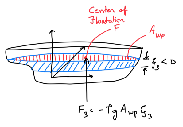
Note that the restoring force acts (upwards) in the direction opposite to the displacement (downward as \(\xi_3<0\)) and hence there is a minus sign in \(\eqref{eq-heave-heave-restoring}\). The corresponding force in the BCS is given by:
\[\begin{align} \begin{bmatrix} \tau_{hst,1} \\ \tau_{hst,2} \\ \tau_{hst,3} \end{bmatrix} = \boldsymbol{R}(\{\eta_{2m}\})^T\begin{bmatrix} 0 \\ 0 \\ F_3 \end{bmatrix} = \begin{bmatrix} -s_{2m} \\ s_{1m} c_{2m} \\ c_{1m} c_{2m} \end{bmatrix} F_3 \end{align}\]
Keeping terms upto the linear order leads to:
\[\begin{align} \begin{bmatrix} \tau_{hst,1} \\ \tau_{hst,2} \\ \tau_{hst,3} \end{bmatrix} = -\rho g A_{WP} \begin{bmatrix} 0 \\ 0 \\ 1 \end{bmatrix} \xi_3 \end{align}\]
This additional buoyancy force acts at the centroid of the additional volume of water displaced. For a small displacement \(\xi_3\), this centroid is equivalent to the centroid of the waterplane area. The centroid of the waterplane area is known as the center of floatation \(F\). Note that center of floatation \(F\) will in general will not coincide with the origin of the BCS and hence there will be a moment due to this force. If the location of \(F\) in BCS is given by \(\vec{r}_F = (x_F, y_F, z_F)\), then the restoring moment is given by:
\[\begin{align} \begin{bmatrix} \tau_{hst,4} \\ \tau_{hst,5} \\ \tau_{hst,6} \end{bmatrix} = \vec{r}_F \times \boldsymbol{R}(\{\eta_{2m}\})^T\begin{bmatrix} 0 \\ 0 \\ F_3 \end{bmatrix} = -\rho g A_{WP} \begin{bmatrix} y_F \\ - x_F \\ 0 \end{bmatrix} \xi_3 \end{align}\]
Thus the generalized hydrostatic force vector is given by:
\[\begin{align} \begin{bmatrix} \tau_{hst,1} \\ \tau_{hst,2} \\ \tau_{hst,3} \\ \tau_{hst,4} \\ \tau_{hst,5} \\ \tau_{hst,6} \end{bmatrix} = -\rho g A_{WP} \begin{bmatrix} 0 \\ 0 \\ 1 \\ y_F \\ - x_F \\ 0 \end{bmatrix} \xi_3 \end{align}\]
If the orientation of the BCS axis with respect the body is chosen in such a way that in the mean equilibruim position the vessel has zero roll and pitch angles \((\phi_m = \theta_m = 0)\), then the hydrostatic generalized force vector due to heave displacement reduces to:
\[\begin{align} \begin{bmatrix} \tau_{hst,1} \\ \tau_{hst,2} \\ \tau_{hst,3} \\ \tau_{hst,4} \\ \tau_{hst,5} \\ \tau_{hst,6} \end{bmatrix} = \begin{bmatrix} 0 \\ 0 \\ 1 \\ y_F \\ - x_F\\ 0 \end{bmatrix} F_3 = -\rho g A_{WP} \begin{bmatrix} 0 \\ 0 \\ 1 \\ y_F \\ -x_F \\ 0 \end{bmatrix} \xi_3 \end{align}\]
Defining \(I_x^A = \iint_{A_{WP}} x dA\) and \(I_y^A = \iint_{A_{WP}} y dA\), the generalized force reduces to:
\[\begin{align} \begin{bmatrix} \tau_{hst,1} \\ \tau_{hst,2} \\ \tau_{hst,3} \\ \tau_{hst,4} \\ \tau_{hst,5} \\ \tau_{hst,6} \end{bmatrix} = - \rho g \begin{bmatrix} 0 \\ 0 \\ A_{WP} \\ I_y^A \\ -I_x^A\\ 0 \end{bmatrix} \xi_3 \end{align}\]
6.3.2 Restoring Force and Moment due to Pitch/Roll Displacements
Consider a freely floating body as shown in Figure 6.2 (a) that is displaced in pitch by \(\xi_5>0\). Note that here it is assumed that the BCS is chosen in such a way that \(\phi_m = \theta_m = 0\). The small pitch displacement will change the instantaneous underwater volume by \(\Delta V = \iint_{A_{WP}} x \xi_5 dA = I_x^A \xi_5\) where \(I_x^A = \iint_{A_{WP}} x dA = x_F A_{WP}\). If the pitch displacement is small then the net restoring force acting on the body can be expressed as:
\[\begin{align} F_3 = \rho g \iint_{A_{WP}} x \xi_5 dA = \rho g x_F A_{WP} \xi_5 = \rho g I_x^A \end{align}\]
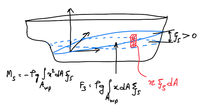
The corresponding moment generated by this additional buoyancy can be expressed as:
\[\begin{align} M_5 = - \rho g \iint_{A_{WP}} x^2 \xi_5 dA = - \rho g \nabla BM_L \xi_5 \end{align}\]
where \(BM_L\) is the longitudinal metacentric radius given by:
\[\begin{align} BM_L = \frac{\iint_{A_{WP}} x^2 dA}{\nabla} = \frac{I_{xx}^A}{\nabla} \end{align}\]
Note that \(I_{xx}^A\) is the second moment of inertia of the waterplane area.
An easy way to understand the sign in the above equations is to consider that case where the body coordinate system is located at the aft end of the vessel. A positive pitch will increase the underwater volume that will result in a positive heave force (upwards). However, this heave force will generate a negative pitch moment (opposing the applied pitch displacement).
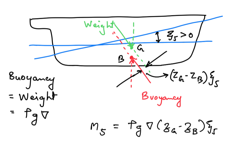
The above analysis has accounted for the forces and moments due to the change in underwater volume. However, one effect is still unaccounted for. The center of gravity \(G\) (with coordinates \((x_G, y_G, z_G)\)) and the center of buoyancy \(B\) (with coordinates \((x_B, y_B, z_B)\)) in a freely floating equilibrium must be in the same vertical line. When the body is pitched, this will no longer be true as shown in Figure 6.2 (b). Therefore the weight and static buoyancy forces will generate pitch moments. This additional pitch moment is given by:
\[\begin{align} M_5 = \rho g \nabla (z_G - z_B) \xi_5 = - \rho g \nabla (KB - KG) \xi_5 \end{align}\]
where \(K\) is the keel of the ship and \(KG\) and \(KB\) refer to the height of the center of gravity and center of buoynacy from the keel respectively. Thus the total pitch moment is given by:
\[\begin{align} M_5 = - \rho g \nabla (BM_L + KB - KG) \xi_5 = - \rho g \nabla GM_L \xi_5 \end{align}\]
Note that \(GM_L\) is known as the longitudinal metacentric height of the vessel. The roll moment caused by this pitch displacement can be calculated as:
\[\begin{align} M_4 = \rho g \iint_{A_{WP}} x y dA \xi_5 = \rho g I_{xy}^A \xi_5 \end{align}\]
where \(I_{xy}^A\) is the cross moment of inertia of the waterplane area. Note that for a ship with port-starboard symmetry \(I_{xy}^A = 0\). The generalized force vector for a small pitch displacement is given by:
\[\begin{align} \begin{bmatrix} \tau_{hst,1} \\ \tau_{hst,2} \\ \tau_{hst,3} \\ \tau_{hst,4} \\ \tau_{hst,5} \\ \tau_{hst,6} \end{bmatrix} = -\rho g\begin{bmatrix} 0 \\ 0 \\ -I_x^A \\ -I_{xy}^A \\ \nabla GM_L\\ 0 \end{bmatrix} \xi_5 \end{align}\]
A similar analysis for a small roll displacement \(\xi_4\) will result in a generalized force vector given by:
\[\begin{align} \begin{bmatrix} \tau_{hst,1} \\ \tau_{hst,2} \\ \tau_{hst,3} \\ \tau_{hst,4} \\ \tau_{hst,5} \\ \tau_{hst,6} \end{bmatrix} = -\rho g\begin{bmatrix} 0 \\ 0 \\ I_y^A \\ \nabla GM_T\\ -I_{xy}^A \\ 0 \end{bmatrix} \xi_4 \end{align}\]
where \(GM_T\) is the transverse metacentric height of the vessel.
6.3.3 Interactive Simulation: Where the \(G\)-\(B\) Moment Comes From
The step that most often causes difficulty is the second one above — the claim that the weight and the buoyancy generate a pitch moment \(\rho g \nabla (z_G - z_B) \xi_5\) once the body is displaced. The buoyancy still equals the weight, so why should two equal and opposite forces produce a moment at all?
The resolution is a matter of which frame you draw the picture in. The weight and the buoyancy are always vertical in the GCS — gravity does not tilt when the ship tilts, and neither does the direction in which pressure pushes the hull up. What the pitch displacement does is carry the points \(G\) and \(B\) around with the body. Two forces that are equal, opposite and vertical produce zero net force but a non-zero couple as soon as their lines of action are separated, and after a rotation \(\xi_5\) the points \(G\) and \(B\) — which started on one vertical line — are separated horizontally by \((z_G - z_B)\xi_5\). That horizontal separation is the lever, and \(\rho g \nabla\) is the force, which is exactly the moment quoted above.
Figure 6.2 (b) draws this in the BCS, with the hull upright and the arrows tilted. That is a perfectly correct picture, but it hides the mechanism, because in it the forces look as though they have rotated. Use the frame toggle in the tool below to switch the same instant between the two views:
- GCS view — the water is level, the hull is heeled, and both arrows are drawn strictly vertical. The lever between the two lines of action is directly visible.
- BCS view — the hull is upright and the waterline is tilted, so the arrows now appear to lean. This reproduces Figure 6.2 (b).
Nothing physical changes between the two; only the frame changes. Switching back and forth is the quickest way to see that the \(G\)-\(B\) moment is not an extra assumption but an unavoidable consequence of rotating the body under two vertical forces.
The tool also separates the two contributions that add up to \(GM\), and connects both of them to the waterplane integrals of the previous sections:
- The wedge term \(-\rho g \nabla BM_L \xi_5\) comes from the emerged and immersed wedges (shaded red and blue in the section view). Its size is set by \(I_{xx}^A = \iint_{A_{WP}} x^2 dA\), which is why the plan view shades each strip of the waterplane by its contribution to that integral. This term shifts \(B\) sideways to \(B'\).
- The \(G\)-\(B\) couple \(-\rho g \nabla (KB - KG)\xi_5\) comes from the vertical separation of \(G\) and \(B\), and does not involve the waterplane at all. Raise \(KG\) above \(KB\) and watch this term change sign.
Two distinct points are marked in the section view, and it is worth being clear about the difference between them. The BCS origin \(O\) (black crosshair) is the point the rotation \(\xi_5\) is defined about: the hull turns bodily about \(O\), and the arc labelled \(\xi_5\) is drawn there. The centre of flotation \(F\) (purple ring) is the centroid of the waterplane, and it is the point the waterline tips about, because \(F\) is the one point of the waterplane whose immersion is unchanged to first order. For the rectangular barge the two coincide and the distinction is invisible; select the ship-like or wedge waterplane and they separate visibly, since \(x_F = I_x^A / A_{WP} \ne 0\). That separation is precisely what the \(I_x^A\) entries of the stiffness matrix are keeping track of — they are the terms coupling heave to pitch, and they vanish only when \(O\) is placed at \(F\).
Switch each term off in turn to see how much of the restoring moment it is responsible for. Note that the wedge term is always stabilising, whereas the \(G\)-\(B\) term is stabilising only when \(G\) lies below \(B\); for a real ship \(G\) is almost always above \(B\), so the \(G\)-\(B\) term is destabilising and the vessel is stable only because the wedge term is larger. Raising \(KG\) far enough drives \(GM_T\) negative and the vessel becomes unstable — try the wedge hull at a high \(KG\) in roll.
Finally, the stiffness matrix \(\boldsymbol{C}\) of the next section is assembled live at the bottom of the tool. The column being excited is highlighted in yellow. The entries shaded red are the coupling terms \(I_x^A\), \(I_y^A\) and \(I_{xy}^A\): these vanish for a hull whose waterplane is symmetric about the BCS origin, and the asymmetry slider bends the waterplane off the centreline so you can watch \(I_{xy}^A\) — and with it the roll-pitch coupling \(C_{45} = C_{54}\) — switch on.
Weight \(W = \rho g \nabla\) through \(G\)
Buoyancy \(F_B = \rho g \nabla\) through \(B\)
Wedge shift \(B \rightarrow B'\)
\(O\) — BCS origin, the point the rotation is about
\(F\) — centre of flotation, the point the waterline tips about
Section view — the lever between the two lines of action
Waterplane — the source of the wedge term
1. Wedge (change of underwater volume)
Set by the waterplane inertia. Always stabilising.
2. \(G\)-\(B\) couple (two vertical forces, offset lines of action)
Total restoring moment
Negative opposes the displacement, so the vessel is stable.
\(A_{WP}\) m²
\(I_x^A = \iint x\,dA\) m³
\(I_y^A = \iint y\,dA\) m³
\(I_{xx}^A = \iint x^2 dA\) m⁴
\(I_{yy}^A = \iint y^2 dA\) m⁴
\(I_{xy}^A = \iint xy\,dA\) m⁴
\(\nabla\) m³
\(x_F\) m
\(KB\) m
\(= I/\nabla\) m
m
Yellow: the column being excited. Red: coupling entries that exist only
when the waterplane is asymmetric about the BCS origin.
6.3.4 Generalized Restoring Forces and Moments
Combining the generalized force vectors from heave, roll and pitch motions yields the generalized force vector that can be expressed as a matrix multiplication of the stiffness matrix \(\boldsymbol{C}\) with the displacement vector \(\{\xi\}\) as shown below:
\[\begin{align} \{\tau_H\} = -\rho g\begin{bmatrix} 0 & 0 & 0 & 0 & 0 & 0 \\ 0 & 0 & 0 & 0 & 0 & 0 \\ 0 & 0 & A_{WP} & I_y^A & -I_x^A & 0 \\ 0 & 0 & I_y^A & \nabla GM_T & -I_{xy}^A & 0 \\ 0 & 0 & -I_x^A & -I_{xy}^A & \nabla GM_L & 0 \\ 0 & 0 & 0 & 0 & 0 & 0 \\ \end{bmatrix} \begin{bmatrix} \xi_1 \\ \xi_2 \\ \xi_3 \\ \xi_4 \\ \xi_5 \\ \xi_6 \end{bmatrix} = -\boldsymbol{C} \{\xi\} \end{align}\]
The stiffness matrix \(\boldsymbol{C}\) is given by:
\[\begin{align} \boldsymbol{C} = \rho g \begin{bmatrix} 0 & 0 & 0 & 0 & 0 & 0 \\ 0 & 0 & 0 & 0 & 0 & 0 \\ 0 & 0 & A_{WP} & I_y^A & -I_x^A & 0 \\ 0 & 0 & I_y^A & \nabla GM_T & -I_{xy}^A & 0 \\ 0 & 0 & -I_x^A & -I_{xy}^A & \nabla GM_L & 0 \\ 0 & 0 & 0 & 0 & 0 & 0 \\ \end{bmatrix} \end{align}\]
6.4 Hydrodynamic Forces and Moments in Calm Waters
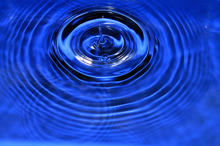
When a pebble is dropped into a calm water body, the water surface is disturbed and ripples are formed as shown in Figure 6.3. Similar waves are also produced when a floating body is moved from its equilibrium position on an initially calm water surface. These waves generated by the motion of the body are known as radiated waves. The force acting on the body due to these waves is known as the radiation force. Whenever a floating body experiences dynamic motion, waves are radiated and the body experiences the radiation force.
A structure in a dynamic fluid medium experiences two types of stress on its surface:
- Normal stress known as the pressure \(p\)
- Stress due to viscosity \(\boldsymbol{\tau} \hat{n}\)
Note that the normal stress due to pressure only acts perpendicular to the local surface. On the contrary the viscous stress has all three components - both the normal as well as two orthogonal tangential components with \(\boldsymbol{\tau}\) being a tensor defined as:
\[\begin{align} \boldsymbol{\tau} = \begin{bmatrix} \tau_{xx} & \tau_{xy} & \tau_{xz} \\ \tau_{yx} & \tau_{yy} & \tau_{yz} \\ \tau_{zx} & \tau_{zy} & \tau_{zz} \end{bmatrix} = \mu \begin{bmatrix} 2\frac{\partial u_1}{\partial x} & \left(\frac{\partial u_1}{\partial y} + \frac{\partial u_2}{\partial x}\right) & \left(\frac{\partial u_1}{\partial z} + \frac{\partial u_3}{\partial x}\right) \\ \left(\frac{\partial u_2}{\partial x} + \frac{\partial u_1}{\partial y}\right) & 2\frac{\partial u_2}{\partial y} & \left(\frac{\partial u_2}{\partial z} + \frac{\partial u_3}{\partial x}\right) \\ \left(\frac{\partial u_3}{\partial x} + \frac{\partial u_1}{\partial z}\right) & \left(\frac{\partial u_3}{\partial y} + \frac{\partial u_2}{\partial y}\right) & 2\frac{\partial u_3}{\partial z} \end{bmatrix} \end{align}\]
The net force on the structure is obtained by integrating the pressure and the wall shear stress across the surface \(S\) of the structure exposed to the fluid as shown below:
\[\begin{align} \vec{F} = \iint_S p\hat{n} dS - \iint_S \boldsymbol{\tau}\hat{n} dS \end{align}\]
where \(\hat{n}\) is the vector normal to the body surface pointing out of the fluid.
6.4.1 Dimensional Analysis of Viscous and Pressure Forces
A floating body oscillating in a calm water produces waves of the similar length as the characteristic length of the body \(L\). Assuming that the wavelength \(\lambda \sim L\) and an amplitude \(a\), the order of the pressure due to a wave can be estimated as
\[\begin{align} p \sim \rho g a \end{align}\]
The order of force acting on the body due to this pressure around the hull can be estimated as
\[\begin{align} F_p \sim \rho g a L^2 \end{align}\]
Now let’s consider the viscous forces. At the hull boundary, the order of the wall shear stress is given by
\[\begin{align} \boldsymbol{\tau} \sim \mu \frac{U}{\delta} \end{align}\]
where \(U\) is the characteristic velocity and \(\delta\) is the boundary layer thickness. The order of the viscous force is given by
\[\begin{align} F_v \sim \tau L^2 \sim \mu \frac{U}{\delta} L^2 \end{align}\]
A water particle in a wave experiences an orbital velocity \(U \sim a \omega\). Thus the ratio of the viscous to pressure forces can be estimated as
\[\begin{align} \frac{F_v}{F_p} \sim \frac{\mu \omega}{\rho g \delta} \sim \frac{\nu \omega}{g \delta} \label{eq-visc-pres-ratio} \end{align}\]
where \(\nu\) is the kinematic viscosity of the water. The order of the boundary layer thickness can also be estimated by considering force balance inside the boundary layer. Consider a fluid velocity parallel to a flat plate is oscillating with
\[\begin{align} u_1 = u_1(t, y) \end{align}\]
where the flat plate is assumed to be in the \(x\)-\(z\) plane and \(y\) is the direction normal to the surface. Neglecting the pressure gradient and the nonlinear convective terms, the \(x\)-momentum equation in the boundary layer can be assumed to be given by
\[\begin{align} \frac{\partial u_1}{\partial t} = \nu \frac{\partial^2 u_1}{\partial y^2} \end{align}\]
Considering the order of the terms, this can be approximated for an order of magnitude comparison as:
\[\begin{align} \frac{U}{1/\omega} \sim \nu \frac{U}{\delta^2} \end{align}\]
Rearranging, we can estimate the order the boundary layer thickness \(\delta\) as
\[\begin{align} \delta \sim \sqrt{\frac{\nu}{\omega}} \end{align}\]
Substituting this in \(\eqref{eq-visc-pres-ratio}\) yeilds:
\[\begin{align} \frac{F_v}{F_p} \sim \frac{\nu \omega}{g \delta} \sim \frac{\nu^{1/2}\omega^{3/2}}{g} \end{align}\]
Consider a ship of length \(100\) meters generating radiated waves of same length. The frequency of this wave can be estimated from the deep water dispersion relationship \(\omega = \sqrt{gk} \approx 0.79~rad/s\). Taking the sea water kinematic viscosity as \(\nu \approx 10^{-6} ~m^2/s\) yields:
\[\begin{align} \frac{F_v}{F_p} \sim \frac{\nu^{1/2}\omega^{3/2}}{g} \approx 10^{-5} \end{align}\]
It can be seen that viscous forces are five orders of magnitude smaller than the pressure forces. Therefore, for the seakeeping analysis, the force on the body is contributed primarily by the pressure term and therefore the fluid can be assumed to be inviscid.
\[\begin{align} \vec{F} = \iint_S p \hat{n} dS \label{eq-pressure-integration} \end{align}\]
6.4.2 Potential Flow
Consider a hull moving steadily with design speed \(U\) in calm waters. We will define a global coordinate system moving steadily forward along its \(x\)-axis with design speed \(U\). Assume that the BCS is also aligned with the GCS in the steady equilibrium condition \((\phi_m = \theta_m = \psi_m = 0)\). When dealing with a floating offshore structure, the design speed \(U=0\). For an inviscid flow, the momentum conservation equations for the fluid flow are given by the Euler equations (Navier Stokes equations with no viscosity):
\[\begin{align} \rho \left(\frac{\partial \vec{V}}{\partial t} + (\vec{V}.\nabla)\vec{V}\right) = -\nabla p + \rho \vec{g} \end{align}\]
where \(\vec{V}\) is the velocity of the fluid in the steadily moving GCS frame. For an offshore structure, the GCS will be stationary. For constant density (incompressible flow), this reduces to
\[\begin{align} \frac{\partial \vec{V}}{\partial t} + (\vec{V}.\nabla)\vec{V} = -\frac{\nabla p}{\rho} - g\nabla z \end{align}\]
Using the vector identity,
\[\begin{align} (\vec{V}.\nabla)\vec{V} = \nabla \left(\frac{|\vec{V}|^2}{2}\right) - \vec{V} \times (\nabla \times \vec{V}) \end{align}\]
the Euler’s equations can be recast as
\[\begin{align} \frac{\partial \vec{V}}{\partial t} + \nabla \left(\frac{|\vec{V}|^2}{2} + \frac{p}{\rho} + g z\right) = \vec{V} \times \vec{\Omega} \label{eq-euler-recast} \end{align}\]
where \(\vec{\Omega}\) is the vorticity. If the flow is irrotational, then \(\vec{\Omega} = 0\) and a total velocity potential \(\Phi\) can be defined as:
\[\begin{align} \vec{V} = \nabla\Phi = - U\hat{i}_0 + \nabla \varphi \label{eq-velocity-potential-def} \end{align}\]
where \(\varphi\) is the disturbance potential and corresponds to the velocity component of the fluid relative to the steady motion of GCS. Substituting this into \(\eqref{eq-euler-recast}\) results in
\[\begin{align} \nabla \left(\frac{\partial \Phi}{\partial t} + \frac{1}{2}\left|\nabla\Phi\right|^2 + \frac{p}{\rho} + g z\right) = 0 \end{align}\]
Expressing in terms of disturbance potential \(\varphi\) results in:
\[\begin{align} \nabla \left(\frac{\partial \varphi}{\partial t} - U \frac{\partial \varphi}{\partial x} + \frac{1}{2}\left|\nabla\varphi\right|^2 + \frac{p}{\rho} + g z\right) = 0 \end{align}\]
This means that the quantity inside the gradient can depend only on time:
\[\begin{align} \frac{\partial \varphi}{\partial t} - U \frac{\partial \varphi}{\partial x} + \frac{1}{2}\left|\nabla\varphi\right|^2 + \frac{p}{\rho} + g z = C(t) \label{eq-bernoulli-unsteady} \end{align}\]
and this expression is known as the unsteady Bernoulli’s equation. The conservation of mass for an incompressible, inviscid flow is given by the continuity equation shown below.
\[\begin{align} \nabla.\vec{V} = 0 \end{align}\]
If the flow is irrotational, a velocity potential \(\varphi\) is defined and the continuity equation reduces to the Laplace equation as shown below:
\[\begin{align} \nabla.\vec{V} = \nabla.(-U\hat{i}_0 + \nabla \varphi) = \nabla^2 \varphi = 0 \label{eq-laplace} \end{align}\]
The Euler’s equations and the continuity equation describe the fluid flow using four equations with four unknowns - pressure \(p\) and three velocities \(u_1\), \(u_2\) and \(u_3\). Under the assumptions of inviscid, incompressible and irrotational flow, a velocity potential \(\varphi\) is admitted that reduces the problem to one governing Laplace equation. Note that the velocities \(u_1\), \(u_2\) and \(u_3\) can be obtained from the gradient of the velocity potential \(\nabla \varphi\) as seen in \(\eqref{eq-velocity-potential-def}\) and the pressure \(p\) is obtained from the unsteady Bernoulli’s equation \(\eqref{eq-bernoulli-unsteady}\).
6.4.3 Boundary Value Problem
In order to compute the hydrodynamic force acting on the body due to the radiated waves generated due to the body motion, we need to know the pressure acting on the hull wetted surface area. If the pressure is known, then it can be integrated to obtain the hydrodynamic force and moment acting on the vessel as seen in \(\eqref{eq-pressure-integration}\). As we have seen, the pressure can be obtained from the Bernoulli’s equation \(\eqref{eq-bernoulli-unsteady}\) if we know the velocity potential \(\varphi\) generated due to the body motion in calm waters. Therefore, the governing Laplace equation \(\eqref{eq-laplace}\) needs to be solved inside the fluid domain to calculate the hydrodynamic force and moment acting on the vessel.
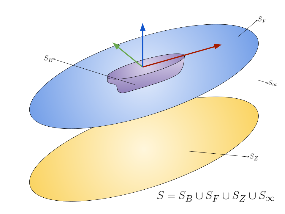
The fluid domain is bounded by the free surface \(S_F\), body boundary \(S_B\) (wetted surface area of the hull), bottom boundary \(S_Z\) and the vertical boundary \(S_{\infty}\) located at an infinite radial distance away from the hull. In order to solve the governing Laplace equation shown in \(\eqref{eq-laplace}\) and obtain the flow parameters inside the domain, we need to impose the boundary conditions on these fluid boundaries.
Kinematic Free Surface Boundary Condition
Consider a particle on the disturbed free surface (due to radiated waves). Let the particle’s position in GCS be denoted by \(\vec{r}_{P}(t) = (x_{P}(t), y_{P}(t), z_{P}(t))\) and let its velocity in GCS be given by \(\vec{V} = (-U + u_1, u_2, u_3)\).
\[\begin{align} \vec{V} = \frac{d}{dt} \vec{r}_{P}(t) \end{align}\]
Let the disturbed free surface be denoted by \(S_F(x, y, z, t) = 0\). However, the particle’s position itself is also time dependent and can explicitly be written as:
\[\begin{align} S_F(x_{P}(t), y_{P}(t), z_{P}(t), t) = 0 \end{align}\]
Therefore, the time derivative of the free surface can be computed using the chain rule of differentiation as:
\[\begin{align} \frac{d S_F}{dt} &= \frac{\partial S_F}{\partial t} + \frac{\partial S_F}{\partial x} \frac{\partial x_P}{\partial t} + \frac{\partial S_F}{\partial y} \frac{\partial y_P}{\partial t} + \frac{\partial S_F}{\partial z} \frac{\partial z_P}{\partial t} \nonumber \\ &= \frac{\partial S_F}{\partial t} + (-U + u_1) \frac{\partial S_F}{\partial x} + u_2 \frac{\partial S_F}{\partial y} + u_3 \frac{\partial S_F}{\partial z} \nonumber \\ &= \left[\frac{\partial}{\partial t} + (\vec{V}.\nabla)\right] S_F \end{align}\]
This operator on the right hand side is also known as the material derivative and is denoted as:
\[\begin{align} \frac{D}{Dt} = \left[\frac{\partial}{\partial t} + (\vec{V}.\nabla)\right] \end{align}\]
Since the free surface is a material surface (a surface made up of the same fluid particles as time evolves), a fluid particle that is initially on the free surface remains on the free surface. If \(S_F(x_P(t_0), y_P(t_0), z_P(t_0), t_0) = 0\) then \(S_F(x_P(t), y_P(t), z_P(t), t) = 0\) for all \(t\). Therefore,
\[\begin{align} \frac{d}{dt} S_F(x_P(t), y_P(t), z_P(t), t) = 0 \end{align}\]
which gives the kinematic free surface boundary condition:
\[\begin{align} \frac{DS_F}{Dt} = \left[\frac{\partial}{\partial t} + (\vec{V}.\nabla)\right] S_F = 0 \end{align}\]
Let the wave elevation be denoted by the function \(\eta(x, y, t)\) defined as the height of the free surface from \(z=0\). The free surface \(S_F\) can then be described as:
\[\begin{align} S_F(x, y, z, t) = z - \eta(x, y, t) \end{align}\]
The kinematic free surface boundary condition can be evaluated as:
\[\begin{align} &\left[\frac{\partial}{\partial t} + (\vec{V}.\nabla)\right] (z - \eta) = 0 \nonumber\\ &u_3 - \frac{\partial \eta}{\partial t} - (-U + u_1) \frac{\partial \eta}{\partial x} - u_2 \frac{\partial \eta}{\partial y} = 0 \nonumber\\ &\frac{\partial \varphi}{\partial z} - \frac{\partial \eta}{\partial t} - \left(-U + \frac{\partial \varphi}{\partial x}\right) \frac{\partial \eta}{\partial x} - \frac{\partial \varphi}{\partial y} \frac{\partial \eta}{\partial y} = 0 \end{align}\]
Thus the kinematic free surface boundary condition is given by:
\[\begin{align} \frac{\partial \eta}{\partial t} - U\frac{\partial \eta}{\partial x} + \frac{\partial \varphi}{\partial x} \frac{\partial \eta}{\partial x} + \frac{\partial \varphi}{\partial y} \frac{\partial \eta}{\partial y} - \frac{\partial \varphi}{\partial z} = 0 \text{ over } z = \eta(x, y, t) \end{align}\]
Notice here that the kinematic boundary condition is applied on the unknown free surface \(z = \eta(x, y, t)\).
Dynamic Free Surface Boundary Condition
This is a second boundary condition imposed on the free surface that the pressure at the interface is equal to the atmospheric pressure \(p_{atm}\). Applying the Bernoulli’s equation on the free surface \(S_F = z - \eta = 0\) yeilds
\[\begin{align} \frac{\partial \varphi}{\partial t} - U \frac{\partial \varphi}{\partial x} + \frac{1}{2}\left|\nabla\varphi\right|^2 + \frac{p_{atm}}{\rho} + g \eta = C(t) \end{align}\]
Without loss of generality, \(C(t)\) can be chosen to be equal to \(p_{atm}/\rho\) so that the dynamic free surface boundary condition is given by:
\[\begin{align} \frac{\partial \varphi}{\partial t} - U \frac{\partial \varphi}{\partial x} + \frac{1}{2}\left|\nabla\varphi\right|^2 + g \eta = 0 \text{ over } z = \eta(x, y, t) \end{align}\]
Vanishing right hand side of Bernoulli’s equation
We have the flexibility to define a new potential \(\tilde{\varphi}\) as
\[\begin{align} \tilde{\varphi} = \varphi - f(t) \end{align}\]
where \(f(t)\) is an arbitrarily chosen function. The partial derivative with time then becomes:
\[\begin{align} \frac{\partial \tilde{\varphi}}{\partial t} = \frac{\partial \varphi}{\partial t} - \frac{df}{dt}(t) \end{align}\]
Notice that the velocity \(\nabla \tilde{\varphi} = \nabla \varphi\) remains unchanged. Therefore, \(f(t)\) can be chosen such that the right hand side of the unsteady Bernoulli’s equation vanishes. Thus the dynamic free surface boundary condition is commonly written as:
\[\begin{align} \frac{\partial \varphi}{\partial t} - U \frac{\partial \varphi}{\partial x} + \frac{1}{2}\left|\nabla\varphi\right|^2 + g \eta = 0 \text{ over } z = \eta(x, y, t) \end{align}\]
Bottom Boundary Condition
At the seabed the imposed condition is that no penetration condition. This means that the fluid should have no normal velocity at the seabed. This is specified mathematically as:
\[\begin{align} \frac{\partial \varphi}{\partial z} = 0 \text{ over } z = -h \end{align}\]
If we are dealing ships and offshore structures operating in deep waters, then this condition is imposed on \(z=-\infty\).
Radiation Boundary Condition
At the infinite boundary \(S_{\infty}\), the waves generated from the body must be propagating outwards towards the infinite boundary. This is enforced by applying the Sommerfield radiation boundary condition on \(S_{\infty}\):
\[\begin{align} \lim_{r\rightarrow\infty} \sqrt{r}\left[\frac{\partial \varphi}{\partial r} - i k \varphi\right] = 0 \end{align}\]
where \(r = \sqrt{x^2 + y^2}\) is the radial horizontal distance and \(k\) is the wavenumber of the outgoing wave.
Body Boundary Condition
This is the most crucial boundary condition as it related the rigid body motion to the hydrodynamic boundary value problem. Since we are now dealing with inviscid flow (as viscous effects are negligible) the boundary condition imposed on the hull boundary is no penetration boundary condition. This is similar to the bottom boundary but with the difference that the boundary is moving. Mathematically the body boundary condition can be specified as:
\[\begin{align} (\vec{V}_s - \nabla \Phi).\hat{n} = 0 \text{ over } S_B(t) \end{align}\]
over the instantaneous underwater surface \(S_B(t)\). Note that \(\vec{V}_s\) represents the local velocity on the ship hull and differs from point to point as the vessel experiences both translational velocity \(\dot{\vec{\xi}}_{t} = \begin{bmatrix}\dot{\xi}_1 & \dot{\xi}_1 & \dot{\xi}_3 \end{bmatrix}^T\) as well as angular velocity \(\dot{\vec{\xi}}_{r} = \begin{bmatrix}\dot{\xi}_4 & \dot{\xi}_5 & \dot{\xi}_6 \end{bmatrix}^T\). Here we are making use of the assumption of small amplitude of motion and velocity. Expanding in terms of the disturbance potential \(\varphi\) yeilds:
\[\begin{align} \frac{\partial \varphi}{\partial n} \equiv \nabla \varphi . \hat{n} = (\dot{\vec{\xi}}_{t} + \dot{\vec{\xi}}_{r} \times \vec{r}_{P}).\hat{n} - \nabla(-Ux).\hat{n} \text{ over } S_B(t) \end{align}\]
where \(\vec{r}_{P}\) denotes the vector from BCS origin to a point \(P\) on the underwater hull surface \(S_B(t)\). Note that \(\hat{n}\) represents the instantaneous normal at point \(P\) on the hull surface that changes with time due to the motion of the vessel.
Boundary Value Problem Summary
Summarizing the boundary value problem, the governing equation is given by:
\[\begin{align} \nabla^2 \varphi = 0 \end{align}\]
with the following boundary conditions:
\[\begin{align} \frac{\partial \eta}{\partial t} - U\frac{\partial \eta}{\partial x} + \frac{\partial \varphi}{\partial x} \frac{\partial \eta}{\partial x} + \frac{\partial \varphi}{\partial y} \frac{\partial \eta}{\partial y} - \frac{\partial \varphi}{\partial z} = 0 \text{ over } z = \eta(x, y, t) \end{align}\]
\[\begin{align} \frac{\partial \varphi}{\partial t} - U \frac{\partial \varphi}{\partial x} + \frac{1}{2}\left|\nabla\varphi\right|^2 + g \eta = 0 \text{ over } z = \eta(x, y, t) \end{align}\]
\[\begin{align} \frac{\partial \varphi}{\partial z} = 0 \text{ over } S_Z = z + h = 0 \end{align}\]
\[\begin{align} \lim_{r\rightarrow\infty} \sqrt{r}\left[\frac{\partial \varphi}{\partial r} - i k \varphi\right] = 0 \text{ over } S_{\infty} \end{align}\]
\[\begin{align} \frac{\partial \varphi}{\partial n} = (\dot{\vec{\xi}}_{t} + \dot{\vec{\xi}}_{r} \times \vec{r}_{P}).\hat{n} - \nabla(-Ux).\hat{n} \text{ over } S_B(t) \end{align}\]
Note that while the govering equation is linear, the free surface and body boundary conditions are not. The body boundary condition couples the motion of the rigid body strongly with the hydrodynamic problem. It is not possible to obtain an exact analytical closed form solution to this boundary value problem. In order to make the problem tenable, we will linearize the boundary conditions and use the principle of superposition (from Chapter 2 and Chapter 3) to separate the problem into 6 sub-problems.
6.4.4 Linearized Boundary Value Problem
As the nonlinear boundary value problem cannot be solved analytically, we employ an approach known as perturbation theory to separate the problem into a series of problems of increasing order of nonlinearity. The solution \(\varphi\) and other parameters of interest (wave elevation \(\eta\), pressure \(p\), normal vector \(\hat{n}\), position vector \(\vec{r}_P\), rigid body displacement \(\xi_k\) for \(k=1,2,...,6\)) are expressed as series expansion in terms of a small quantity \(\epsilon\) (usually of the order of wave slope).
\[\begin{align} \varphi &= \epsilon \varphi^{(1)} + \epsilon^2 \varphi^{(2)} + ~ ... \\ \eta &= \epsilon \eta^{(1)} + \epsilon^2 \eta^{(2)} + ~ ... \\ p &= p^{(0)} + \epsilon p^{(1)} + \epsilon^2 p^{(2)} + ~ ... \\ \hat{n} &= \hat{n}^{(0)} + \epsilon \hat{n}^{(1)} + \epsilon^2 \hat{n}^{(2)} + ~ ... \\ \vec{r}_P &= \vec{r}_P^{(0)} + \epsilon \vec{r}_P^{(1)} + \epsilon^2 \vec{r}_P^{(2)} + ~ ... \\ \xi_k &= \epsilon \xi_k^{(1)} + \epsilon^2 \xi_k^{(2)} + ~ ... \text{ for } k =1,2,...,6 \end{align}\]
Substituting this into the governing equation and the boundary conditions results in the problem being reduced to solving successive set of Laplace equations for each order of \(\epsilon\). The boundary value problem for \(\varphi^{(1)}\) is obtained by only keeping terms upto the first order of \(\epsilon\) and is given by:
\[\begin{align} \nabla^2 \varphi^{(1)} = 0 \end{align}\]
\[\begin{align} \frac{\partial \varphi^{(1)}}{\partial t} - U \frac{\partial \varphi^{(1)}}{\partial x} + g \eta = 0 \text{ over } z = 0 \end{align}\]
\[\begin{align} \frac{\partial \eta^{(1)}}{\partial t} - U\frac{\partial \eta^{(1)}}{\partial x} - \frac{\partial \varphi^{(1)}}{\partial z} = 0 \text{ over } z = 0 \end{align}\]
\[\begin{align} \frac{\partial \varphi^{(1)}}{\partial z} = 0 \text{ over } S_Z = z + h = 0 \end{align}\]
\[\begin{align} \lim_{r\rightarrow\infty} \sqrt{r}\left[\frac{\partial \varphi^{(1)}}{\partial r} - i k \varphi^{(1)}\right] = 0 \text{ over } S_{\infty} \end{align}\]
The body boundary condition when linearized yeilds
\[\begin{align} \frac{\partial \varphi^{(1)}}{\partial n} = \sum_{k=1}^{6} \dot{\xi}_k^{(1)} n_k + \xi_k^{(1)} m_k \text{ over } S_{B0} \end{align}\]
where
\[\begin{align} (n_1, n_2, n_3) &= \hat{n}^{(0)} \\ (n_4, n_5, n_6) &= \vec{r}_P^{(0)} \times \hat{n}^{(0)} \\ (m_1, m_2, m_3) &= -(\hat{n}^{(0)}.\nabla) \vec{W} \\ (m_4, m_5, m_6) &= -(\hat{n}^{(0)}.\nabla) (\vec{r}_P^{(0)} \times \vec{W}) \end{align}\]
\(\vec{W} = -U\hat{i}_0\) is the steady flow around the hull and \(S_{B0}\) is the surface of the hull in its equilibrium position \((\{\xi\} = 0)\). The linearized potential \(\varphi^{(1)}\) is the potential caused due to the small amplitude motion of the rigid body along the six degrees of freedom. However, since the boundary value problem is now linear, we can separate the potential into six components (one for each degree of freedom).
\[\begin{align} \varphi^{(1)} = \sum_{k=1}^{6} \tilde{\varphi}_k^{(1)} \label{eq-potential-superposition} \end{align}\]
Thus the same linearized boundary value problem can be solved for each of the \(\tilde{\varphi}_k^{(1)}\) for \(k=1,2,...,6\) with the boundary condition for each \(\tilde{\varphi}_k^{(1)}\) specified as:
\[\begin{align} \frac{\partial \tilde{\varphi}_k^{(1)}}{\partial n} = \dot{\xi}_k^{(1)} n_k + \xi_k^{(1)} m_k \text{ over } S_{B0} \end{align}\]
Notice that the rigid body motions \(\xi_k^{(1)}(t)\), even though of small amplitude, is coupled to the hydrodynamic problem. \(\tilde{\varphi}_k^{(1)}\) depends on \(\xi_k^{(1)}\) and viceversa. In order to separate the hydrodynamic and rigid body motion problems, we define the potential \(\varphi_k^{(1)}\) caused due to an impulsive displacement \(\xi_k^{(1)}(t) = \delta(t)\). The potential \(\tilde{\varphi}_k^{(1)}(t)\) for a generic \(\xi_k^{(1)}(t)\) can then be expressed in terms of a convolution integral as:
\[\begin{align} \tilde{\varphi}_k^{(1)}(t) = \int_{-\infty}^{t} \varphi_k^{(1)}(t-\tau) \xi_k^{(1)}(\tau) d\tau \end{align}\]
Taking a Fourier transform yields:
\[\begin{align} \hat{\tilde{\varphi}}_k^{(1)} (\omega) = \hat{\varphi}_k^{(1)}(\omega) \xi_k^{(1)}(\omega) \label{eq-impulsive-potential-fourier} \end{align}\]
In the frequency domain we deal with solving the boundary value problem only for a single frequency at a time. Taking a Fourier transform of the boundary value problem for \(\varphi^{(1)}\) and using \(\eqref{eq-potential-superposition}\) and \(\eqref{eq-impulsive-potential-fourier}\) yields the governing equation:
\[\begin{align} \nabla^2 \hat{\varphi}_k^{(1)} = 0 \end{align}\]
combined free surface boundary condition:
\[\begin{align} \left(i \omega - U \frac{\partial }{\partial x}\right)^2 \hat{\varphi}_k^{(1)} + g \frac{\partial \hat{\varphi}_k^{(1)}}{\partial z} = 0 \text{ over } z = 0 \end{align}\]
bottom boundary condition:
\[\begin{align} \frac{\partial \hat{\varphi}_k^{(1)}}{\partial z} = 0 \text{ over } S_Z = z + h = 0 \end{align}\]
radiation boundary condition:
\[\begin{align} \lim_{r\rightarrow\infty} \sqrt{r}\left[\frac{\partial \hat{\varphi}_k^{(1)}}{\partial r} - i k \hat{\varphi}_k^{(1)}\right] = 0 \text{ over } S_{\infty} \end{align}\]
and body boundary condition:
\[\begin{align} \frac{\partial \hat{\varphi}_k^{(1)}}{\partial n} = (i \omega n_k + m_k) \text{ over } S_{B0} \end{align}\]
where \(\hat{\varphi}_k^{(1)} = \mathcal{F}\left(\varphi_k^{(1)}\right)\). Note that by taking the Fourier transform of the linearized boundary value problem, an arbitrary small amplitude rigid body motion of the vessel has been separated into infinitely many sinusoidal motions at various continuous frequencies \(\omega\).
Interactive Anatomy of the Boundary Value Problem
Figure 6.4 names the four boundaries; the tool below attaches the mathematics to each of them. Click a surface in the diagram — or a tab — to see the condition imposed there, what it physically asserts, and what happens to it under linearisation.
The Exact / Linearised toggle is the part worth spending time on. Switching between the two shows, boundary by boundary, precisely which terms perturbation theory throws away and, more importantly, where each condition is applied. Two observations that are easy to state but hard to see in a static figure:
- The governing equation is never linearised. Laplace’s equation is already linear, and every order of the perturbation series satisfies the identical equation. Select the fluid domain and toggle: nothing changes. All of the approximation in this chapter lives in the boundary conditions.
- Only two boundaries actually move, and they are exactly the two that cause trouble. The seabed and the far field are fixed, and their conditions pass through linearisation untouched. The free surface condition is imposed on the unknown surface \(z = \eta(x,y,t)\) and is moved to the known plane \(z=0\); the body condition is imposed on the instantaneous wetted surface \(S_B(t)\) and is moved to the mean surface \(S_{B0}\). Those two moves are what turn an intractable problem into six solvable ones.
6.4.5 Solving Linearized Boundary Value Problem
There are different methods to solve the linearized boundary value problem described above. Some of the popular approaches include the boundary element methods and finite element methods. However, the boundary element methods have now emerged as the standard approach to solve this problem due to the advantages of only needing to mesh the fluid boundary (surface) instead of meshing the fluid domain (volume) as required by finite element methods. The discussion of the boundary element methods is beyond the purview of this course.
There are several software tools that have emerged over the years to solve this boundary value problem. Some of the common tools include WAMIT and ANSYS AQWA. My research group (suprisingly several undergraduate students have contributed to this project) has also developed a web application (HydRA) to solve this boundary value problem.
6.4.6 Calculating Hydrodynamic Forces and Moments
Once the linearized boundary value problem has been solved, the potential \(\hat{\varphi}_k^{(1)}\) is known. However, our interest is to calculate the forces and moments acting on the vessel. It was seen previously that the force on the vessel can be obtained by integrating the pressure across the hull. The generalized force \(\{F\}\) acting on the vessel can be evaluated as:
\[\begin{align} \{F\} = \begin{bmatrix} \vec{F} \\ \vec{M} \end{bmatrix} = \begin{bmatrix} \iint_S p \hat{n} dS \\ \iint_S p (\vec{r}_P \times \hat{n}) dS \end{bmatrix} = \text{ over } S_B(t) \end{align}\]
The pressure can be expressed in terms of the potential using the unsteady Bernoulli’s equation and the application of perturbation theory will allow the generalized force to be expressed in orders of \(\epsilon\).
\[\begin{align} \vec{F} &= \vec{F}^{(0)} + \epsilon\vec{F}^{(1)} + \epsilon^2\vec{F}^{(2)} + ~ ... \\ \vec{M} &= \vec{M}^{(0)} + \epsilon\vec{M}^{(1)} + \epsilon^2\vec{M}^{(2)} + ~ ... \end{align}\]
\[\begin{align} \vec{F} &= \iint_{S_B(t)} dS \left[-\rho \left(\frac{\partial \varphi}{\partial t} - U \frac{\partial \varphi}{\partial x} + \frac{1}{2}\left|\nabla\varphi\right|^2 + g z\right) \hat{n}\right] \\ &= \left(\iint_{S_{B0}} dS + \epsilon \iint_{S_{B1}} dS + ~ ...\right) \left[-\rho \left(\left(\frac{\partial }{\partial t} - U \frac{\partial }{\partial x}\right) (\epsilon\varphi^{(1)} + \epsilon^2 \varphi^{(2)} + ~ ...) \right.\right.\nonumber \\ & \quad \left.\left.+ \frac{1}{2}\left|\nabla(\epsilon\varphi^{(1)} + \epsilon^2 \varphi^{(2)} + ~ ...)\right|^2 + g (z^{(0)} + \epsilon z^{(1)} + \epsilon^2 z^{(2)} + ~ ...)\right) \right.\nonumber\\ & \quad \left. .(\epsilon\hat{n}^{(1)} + \epsilon^2 \hat{n}^{(2)} + ~ ...) \right] \end{align}\]
Note that we have expanded the instantaneous wetted surface \(S_B(t)\) into its perturbation series.
\[\begin{align} S_B(t) = S_{B0} + \epsilon S_{B1}(t) + ~ ... \end{align}\]
Collecting the terms by orders of \(\epsilon\) yields the zeroth order force and moments as:
\[\begin{align} \vec{F}^{(0)} &= \iint_{S_{B0}} - \rho g z^{(0)} \hat{n}^{(0)} dS \\ \vec{M}^{(0)} &= \iint_{S_{B0}} - \rho g z^{(0)} (\vec{r}_P^{(0)} \times \hat{n}^{(0)}) dS \\ \end{align}\]
It can be seen that this is just the integration of the hydrostatic pressure over the mean wetted surface area of the hull in its equilibrium position. For a vessel floating at even keel, the hydrostatic force \(\vec{F}^{(0)}\) is the buoyancy force in the equilibrium condition and \(\vec{M}^{(0)}\) is the moment of the buoyancy force about the BCS origin. The buoyancy force will be balanced by the weight and the moment will be balanced by the moment of the weight about the BCS origin. The first order forces and moments can be computed as:
\[\begin{align} \vec{F}^{(1)} &= \iint_{S_{B0}} - \rho \left(\left(\frac{\partial }{\partial t} - U \frac{\partial }{\partial x}\right)\varphi^{(1)} + g z^{(1)}\right) \hat{n}^{(0)} dS \nonumber\\ & \quad + \iint_{S_{B0}} - \rho g z^{(0)} \hat{n}^{(1)} dS + \iint_{S_{B1}} - \rho g z^{(0)} \hat{n}^{(0)} dS \\ \vec{M}^{(1)} &= \iint_{S_{B0}} - \rho \left(\left(\frac{\partial }{\partial t} - U \frac{\partial }{\partial x}\right)\varphi^{(1)} + g z^{(1)}\right) (\vec{r}_P^{(0)} \times \hat{n}^{(0)}) dS \nonumber\\ & \quad + \iint_{S_{B0}} - \rho g z^{(0)} (\vec{r}_P^{(0)} \times \hat{n}^{(1)}) dS + \iint_{S_{B0}} - \rho g z^{(0)} (\vec{r}_P^{(1)} \times \hat{n}^{(0)}) dS \nonumber\\ & \quad + \iint_{S_{B1}} - \rho g z^{(0)} (\vec{r}_P^{(0)} \times \hat{n}^{(0)}) dS \end{align}\]
\(S_{B1}\) is the first order variation of \(S_{B0}\) and the integral over this surface can be represented as:
\[\begin{align} \iint_{S_{B1}} (.) dS = \int_{WL0} \zeta_r^{(1)} (.) dl \end{align}\]
where \(WL0\) is the mean waterline of the vessel in its equilibrium position and \(\zeta_r^{(1)}\) is the first order relative waterlevel and is given by:
\[\begin{align} \zeta_r^{(1)} = \eta^{(1)} - \left(\xi_3^{(1)} - \xi_5^{(1)} x^{(0)} + \xi_4^{(1)} y^{(0)}\right) \end{align}\]
Note that \(z^{(0)} = 0\) on \(WL0\) and the first order force and moment contributions due to the integral over \(S_{B1}\) are zero.
\[\begin{align} \iint_{S_{B1}} &- \rho g z^{(0)} \hat{n}^{(0)} dS = 0 \\ \iint_{S_{B1}} &- \rho g z^{(0)} (\vec{r}_P^{(0)} \times \hat{n}^{(0)}) dS = 0 \end{align}\]
Note that \(z^{(1)}\) is the z-component of the vector \(\vec{r}_P^{(1)}\). Both the normal vector \(\hat{n}\) and the position vector of a point on the hull \(\vec{r}_P\) up to the first order are given by:
\[\begin{align} \vec{r}_P &= \vec{r}_P^{(0)} + \epsilon \left(\vec{\xi}_t^{(1)} + \vec{\xi}_r^{(1)} \times \vec{r}_P^{(0)}\right) + ~ ... \\ \hat{n} &= \hat{n}^{(0)} + \epsilon \left(\vec{\xi}_r^{(1)} \times \hat{n}^{(0)}\right) + ~ ... \end{align}\]
The expression for first order force and first order moment reduce to:
\[\begin{align} \vec{F}^{(1)} &= \vec{F}_{R}^{(1)} + \vec{F}_H^{(1)} \nonumber\\ &= - \rho\iint_{S_{B0}} \left(\frac{\partial }{\partial t} - U \frac{\partial }{\partial x}\right)\varphi^{(1)} \hat{n}^{(0)} dS \nonumber\\ & \quad - \rho g \iint_{S_{B0}} \left(z^{(1)} \hat{n}^{(0)} + z^{(0)} \hat{n}^{(1)}\right) dS \\ \vec{M}^{(1)} &= \vec{M}_{R}^{(1)} + \vec{M}_H^{(1)} \nonumber\\ &= - \rho \iint_{S_{B0}}\left(\frac{\partial }{\partial t} - U \frac{\partial }{\partial x}\right)\varphi^{(1)} (\vec{r}_P^{(0)} \times \hat{n}^{(0)}) dS \nonumber\\ & \quad - \rho g \iint_{S_{B0}} \left(z^{(1)} (\vec{r}_P^{(0)} \times \hat{n}^{(0)}) + z^{(0)} (\vec{r}_P^{(0)} \times \hat{n}^{(1)}) + z^{(0)} (\vec{r}_P^{(1)} \times \hat{n}^{(0)}) \right) dS \end{align}\]
In both the force and moment expressions above, the first integral corresponds to the hydrodynamic force or moment due to the radiated wave (depends on \(\varphi^{(1)}\)) and the second term corresponds to the hydrostatic force or moment discussed previously. It can be shown that the hydrostatic component is the same as derived before:
\[\begin{align} \begin{bmatrix} \vec{F}_H^{(1)} \\ \vec{M}_H^{(1)} \end{bmatrix} &= -\rho g \begin{bmatrix} 0 & 0 & 0 & 0 & 0 & 0 \\ 0 & 0 & 0 & 0 & 0 & 0 \\ 0 & 0 & A_{WP} & I_y^A & -I_x^A & 0 \\ 0 & 0 & I_y^A & \nabla GM_T & -I_{xy}^A & 0 \\ 0 & 0 & -I_x^A & -I_{xy}^A & \nabla GM_L & 0 \\ 0 & 0 & 0 & 0 & 0 & 0 \end{bmatrix} \begin{bmatrix} \xi_1 \\ \xi_2 \\ \xi_3 \\ \xi_4 \\ \xi_5 \\ \xi_6 \end{bmatrix} = -\boldsymbol{C} \{\xi\} \label{eq-hydrostatics-1} \end{align}\]
Thus the hydrodynamic force can be expressed as:
\[\begin{align} \vec{F}_{R}^{(1)} &= - \rho\iint_{S_{B0}} \left(\frac{\partial }{\partial t} - U \frac{\partial }{\partial x}\right)\varphi^{(1)} \hat{n}^{(0)} dS \\ &= - \rho \sum_{k=1}^{6} \iint_{S_{B0}} \left(\frac{\partial }{\partial t} - U \frac{\partial }{\partial x}\right)\tilde{\varphi}_k^{(1)} \hat{n}^{(0)} dS\\ \vec{M}_{R}^{(1)} &= - \rho \iint_{S_{B0}} \left(\frac{\partial }{\partial t} - U \frac{\partial }{\partial x}\right)\varphi^{(1)} (\vec{r}_P^{(0)} \times \hat{n}^{(0)}) dS \\ &= - \rho \sum_{k=1}^{6} \iint_{S_{B0}} \left(\frac{\partial }{\partial t} - U \frac{\partial }{\partial x}\right)\tilde{\varphi}_k^{(1)} (\vec{r}_P^{(0)} \times \hat{n}^{(0)}) dS \end{align}\]
Taking a Fourier transform leads to:
\[\begin{align} \left\{\hat{\tau}_R(\omega)\right\} = \begin{bmatrix} \hat{\vec{F}}_R^{(1)} (\omega) \\ \hat{\vec{M}}_R^{(1)} (\omega) \end{bmatrix} = -\rho \sum_{k=1}^{6} \begin{bmatrix} \iint_{S_{B0}} \left(i\omega - U \frac{\partial }{\partial x}\right)\hat{\varphi}_k^{(1)} \hat{\xi}_k^{(1)} \hat{n}^{(0)} dS \\ \iint_{S_{B0}} \left(i\omega - U \frac{\partial }{\partial x}\right)\hat{\varphi}_k^{(1)} \hat{\xi}_k^{(1)} (\vec{r}_P^{(0)} \times \hat{n}^{(0)}) dS \end{bmatrix} \end{align}\]
The radiation force and moment can be separated into components proportional to the acceleration \(-\omega^2 \xi_k^{(1)}\) and velocity \(i\omega \xi_k^{(1)}\) as:
\[\begin{align} \left\{\hat{\tau}_R(\omega)\right\} = -\left(-\omega^2 \boldsymbol{A}(\omega) \left\{\hat{\xi}\right\} + i \omega \boldsymbol{B}(\omega) \left\{\hat{\xi}\right\}\right) \end{align}\]
where the terms of the \(6 \times 6\) matrices \(\boldsymbol{A} = [A_{jk}]\) and \(\boldsymbol{B} = [B_{jk}]\) are given by:
\[\begin{align} A_{jk} (\omega) &= - \frac{\rho}{\omega^2}\operatorname{Re} \left\{ \iint_{S_{B0}} \left(i\omega - U \frac{\partial }{\partial x}\right)\hat{\varphi}_k^{(1)} n_j dS \right\}\\ B_{jk} (\omega) &= \frac{\rho}{\omega} \operatorname{Im} \left\{ \iint_{S_{B0}} \left(i\omega - U \frac{\partial }{\partial x}\right)\hat{\varphi}_k^{(1)} n_j dS \right\} \end{align}\]
Note that \(\boldsymbol{A}(\omega)\) and \(\boldsymbol{B}(\omega)\) are both real matrices. The matrix \(\boldsymbol{A}(\omega)\) is known as the added mass matrix and \(\boldsymbol{B}(\omega)\) is known as the radiation damping matrix. The added mass can notionally be thought of as the inertia due to additional fluid that also experiences acceleration when the rigid body experiences acceleration. The radiation damping can notionally be thought of as the damping corresponding to the energy that the radiated waves take away from the rigid body due to thier propagation away from the body.
Note that both the added mass and radiation damping are frequency dependent. As the frequency of oscillation of the rigid body changes, the inertial and damping effects exhibited by the fluid on the body also change. This is quite different from our previous discussion of spring mass damper systems in Chapter 2, where the mass (inertia) and damping are fixed values and do not depend on the frequency of oscillation.
Interactive Simulation: Frequency Dependence of \(\boldsymbol{A}\) and \(\boldsymbol{B}\)
The tool below makes that statement concrete for a two-dimensional section: a circular cylinder with its axis in the mean free surface, heaving in deep water. All quantities are per unit length. Drag the frequency marker on the slider or directly on any plot.
Where these numbers come from
The coefficients are digitised from published data, not invented. They are read from Fig. 3.6 of Faltinsen (1990), which gives the two-dimensional added mass and damping in heave and sway for exactly this section, using his non-dimensional groups
\[\begin{align} \nu = \frac{\omega^2 R}{g}, \qquad \hat{A}_{33} = \frac{A_{33}^{(2D)}}{\rho A_s}, \qquad \hat{B}_{33} = \frac{B_{33}^{(2D)}}{\rho \omega A_s}, \qquad A_s = \tfrac{1}{2}\pi R^2 \end{align}\]
The radiated wave amplitude ratio \(\bar{A}\) is not read off the figure. It is obtained from the damping through the exact energy statement, Faltinsen’s equation (3.26),
\[\begin{align} B_{33} = \rho \left(\frac{A_3}{|\eta_3|}\right)^2 \frac{g^2}{\omega^3} \qquad \Longrightarrow \qquad \bar{A} \equiv \frac{A_3}{|\eta_3|} = \nu \sqrt{\frac{\pi \hat{B}_{33}}{2}} \label{eq-faltinsen-326} \end{align}\]
which says that the work done against the damping in one cycle equals the energy carried away by the two radiated wave trains. Two consequences are worth noting: this is why \(B_{33}\) can never be negative, whereas the added mass carries no such guarantee and is negative for some sections.
As a check on the digitisation, the added mass and damping columns were traced independently, and \(\hat{A}_{33}\) was then recomputed from \(\hat{B}_{33}\) alone through the Kramers–Kronig relation quoted at the end of this section. It reproduces the traced \(\hat{A}_{33}\) to within \(0.04\) over \(0.2 \le \nu \le 2.2\), and the implied \(\hat{A}_{33}(\infty) = 0.958\) agrees with the theoretical infinite-frequency value of unity to within four percent. Reading accuracy off the printed figure is about \(\pm 0.02\) in \(\hat{A}_{33}\) and \(\pm 0.03\) in \(\hat{B}_{33}\).
Three things are worth chasing:
The radiated wave is drawn to scale. Its height in the animation is literally \(\bar{A}\) times the heave amplitude, with \(\bar{A}\) taken from \(\eqref{eq-faltinsen-326}\). At very low frequency the cylinder moves so slowly that it barely disturbs the surface and \(\bar{A} \rightarrow 0\); the wave you see is genuinely almost flat. As the frequency rises the coupling to the free surface strengthens and \(\bar{A}\) climbs to about \(0.8\). Damping here is not friction — the fluid is inviscid — but the energy carried away by those waves, and \(\eqref{eq-faltinsen-326}\) is the exact bookkeeping.
The heave amplitude slider makes the linearity of the whole theory visible. \(\bar{A}\) is an amplitude ratio, and within linear theory it depends only on frequency and hull shape — not on how far the body moves. So doubling the heave amplitude doubles the radiated wave amplitude exactly, and leaves \(A_{33}\), \(B_{33}\) and \(\omega_n\) completely unchanged. Watch the \(\bar{A}\) readout stay fixed while the radiated amplitude \(A_3 = \bar{A}|\eta_3|\) tracks the slider. This is the same superposition property assumed throughout Chapter 2 and this chapter, and it is precisely what would fail for a large-amplitude motion.
Comparing the plots with Fig. 3.6 directly
The \(B_{33}\) curve here rises to a peak and then decays, whereas the corresponding curve in Fig. 3.6 falls monotonically from \(8/\pi\). Both are correct: they are the same data on different axes. Faltinsen plots the non-dimensional \(\hat{B}_{33} = B_{33}/(\rho\omega A_s)\) against \(\nu = \omega^2 R/g\), and the ordinate itself contains a factor \(\omega\). Since
\[\begin{align} B_{33} = \hat{B}_{33}\,\rho\,\omega A_s \end{align}\]
a monotonically falling \(\hat{B}_{33}\) multiplied by a rising \(\omega\) produces a dimensional curve with an interior maximum. The Axes button switches the two coefficient panels into Faltinsen’s non-dimensional form so they can be laid directly beside the printed figure; the added mass panel then shows \(\hat{A}_{33}\) falling to a minimum near \(\nu \approx 0.8\) and rising slowly towards \(\hat{A}_{33}(\infty)\), exactly as in the book.
The physical reading of the dimensional peak is worth keeping: it is the frequency at which the section couples most strongly to the free surface and so removes energy from the motion fastest.
Added mass is not a mass. \(\hat{A}_{33}\) falls from large values at low frequency to a minimum near \(\nu \approx 0.8\) and then climbs slowly back towards \(\hat{A}_{33}(\infty)\). It has no single value, so the picture of “a fixed lump of entrained water” cannot be literally true: no fixed body of water changes with the frequency at which you shake it. Note also the steep rise as \(\nu \rightarrow 0\). That is not a drawing artefact — for a two-dimensional heaving section the added mass grows without bound at zero frequency, a direct consequence of \(B_{33}\) vanishing only linearly in \(\omega\) there.
The natural frequency becomes a fixed point. For the spring mass damper of Chapter 2, \(\omega_n = \sqrt{k/m}\) is read off in one step. Here the determinant condition at the end of this chapter reduces in one degree of freedom to \(-\omega^2(m' + A_{33}(\omega)) + K' = 0\), and substituting the non-dimensional forms makes the radius cancel entirely:
\[\begin{align} \nu\left(1 + \hat{A}_{33}(\nu)\right) = \frac{4}{\pi} \end{align}\]
so the resonant \(\nu\) is a property of the shape alone. It still cannot be evaluated directly, because \(\hat{A}_{33}\) depends on the \(\nu\) being sought; it must be iterated, and converges to \(\nu_n = 0.815\). The right-hand plot shows the residual, whose zero crossing is the true \(\omega_n\), against the dashed curve obtained by freezing the added mass at \(A_{33}(\infty)\). The gap between the two crossings is the error incurred by ignoring frequency dependence: about twelve percent of the natural period, at every radius.
\(A(\omega)\) — added mass
\(B(\omega)\) — radiation damping
\(\omega_n\) — natural frequency, a fixed point
Added mass \(A_{33}(\omega)\) — drag to change \(\omega\)
Radiation damping \(B_{33}(\omega)\)
Residual — its zero is \(\omega_n\)
\(\omega\)
\(\nu = \omega^2 R/g\)
\(\bar{A} = A_3/|\eta_3|\)
radiated amplitude \(A_3\) m
Period \(T\) s
\(\lambda = 2\pi g/\omega^2\) m
\(A_{33}(\omega)\) kg/m
\(A_{33}(\infty)\) kg/m
\(B_{33}(\omega)\) kg/(m·s)
\(m' = \rho A_s\) kg/m
\(K' = \rho g\,2R\) N/m per m
\(\omega_n\) rad/s
\(T_n\) s
iterations to fixed point
phase speed \(c_p = g/\omega\) m/s
group speed \(c_g = g/2\omega\) m/s
Interactive: Added Mass and Damping of the KCS Container Ship
The cylinder above is two-dimensional and has a single degree of freedom. A ship has six, and the radiation loads form the full \(6 \times 6\) matrices \(\boldsymbol{A}(\omega)\) and \(\boldsymbol{B}(\omega)\) of the previous section. The tool below shows every element of both matrices for the KCS, the MOERI container ship used as a benchmark hull throughout ship hydrodynamics, computed by a three-dimensional panel method.
Where these numbers come from
The coefficients are from a frequency-domain panel-method (HydRA) run on the KCS at full scale — \(L_{pp} = 230\) m, \(B = 32.2\) m, \(T = 10.8\) m, \(\nabla = 52\,030\) m\(^3\), see the SIMMAN 2008 hull description — in deep water, for 50 frequencies \(\omega = 0.03, \ldots, 1.50\) rad/s and three forward speeds: \(U = 0\), \(6.17\) m/s (12 kn, \(Fn = 0.13\)) and \(12.35\) m/s (24 kn, the service speed, \(Fn = 0.26\)). At forward speed the boundary value problem is solved at the encounter frequency \(\omega_e = \omega - (\omega^2/g)U\cos\beta\), so the coefficients at \(U > 0\) depend on the wave heading \(\beta\) through \(\omega_e\); at \(U = 0\) the heading is irrelevant. The same run supplies the wave loads used in Chapter 7. The Scale button switches between dimensional coefficients and the non-dimensional forms \(A_{ij}/(\rho L^k)\) and \(B_{ij}/(\rho\omega L^k)\), with \(L = L_{pp} = 230\) m, \(\omega\) the wave frequency, and \(k = 3\) when both \(i, j\) are translations, \(k = 4\) when one is a rotation and \(k = 5\) when both are.
Pick an element \(ij\) of the matrix — \(A_{ij}\) is the load in mode \(i\) in phase with the acceleration in mode \(j\), \(B_{ij}\) the load in mode \(i\) in phase with the velocity in mode \(j\) — together with a heading. The three speeds are always drawn together, and the Axis button re-plots them against \(\omega_e\).
Three things are worth chasing:
The diagonal. \(A_{33}\) at low frequency is more than three times the mass of the ship, then falls with frequency towards \(A_{33}(\infty)\), the dashed line, which is the coefficient that multiplies \(\ddot{\xi}\) in the Cummins equation below. \(B_{33}\) rises from zero, peaks where the hull radiates most effectively, and decays again; as for the cylinder, it can never be negative, whereas \(A_{ij}\) can. Compare \(A_{11}\), which is only a few percent of the mass: a slender hull pushes little water aside when it surges.
Speed enters through \(\omega_e\) — and then some. Switch to the \(\omega_e\) axis with \(A_{33}\) or \(B_{33}\) selected in head seas: the three curves collapse onto one, because the only thing forward speed did to these elements was change the frequency at which the problem is solved. Now select \(A_{55}\), \(A_{35}\) or \(A_{53}\). They do not collapse. The pressure operator \((i\omega_e - U\,\partial/\partial x)\) adds terms proportional to \(U/\omega_e\) that couple pitch to the heave coefficients, and it breaks the symmetry \(A_{35} \approx A_{53}\) that holds at zero speed. That residual gap is the true forward-speed effect, and it is largest at low \(\omega_e\).
The matrix is nearly block-diagonal. For a hull symmetric about its centreplane the vertical modes (surge, heave, pitch) and the lateral modes (sway, roll, yaw) do not couple at zero speed, so elements such as \(A_{23}\) or \(A_{15}\) are orders of magnitude below the diagonal — the values that do appear there are mesh asymmetry and numerical noise. The couplings that matter are \(A_{35}\), \(A_{53}\) (heave–pitch) and \(A_{24}\), \(A_{26}\), \(A_{46}\) (sway–roll–yaw).
KCS in plan and profile with the heading β used for ωₑ, the service-speed arrow and the wave at the chosen ω. The purple glyph marks the motion mode j.
Values at the marked wave frequency for each speed.
Taking the inverse Fourier transform of \(\{\hat{\tau}_R(\omega)\}\) yields the generalized radiation force in the time domain \(\{\tau_R(t)\}\):
\[\begin{align} \left\{\tau_R(t)\right\} &= \mathcal{F}^{-1} \left(\left\{\hat{\tau}_R(\omega)\right\}\right) \nonumber \\ &= -\mathcal{F}^{-1} \left(-\omega^2 \boldsymbol{A}(\omega) \left\{\hat{\xi}\right\} + i \omega \boldsymbol{B}(\omega) \left\{\hat{\xi}\right\}\right) \nonumber\\ &= - \boldsymbol{A}(\infty) \left\{\ddot{\xi}\right\} - \boldsymbol{B}(\infty) \left\{\dot{\xi}\right\} + \int_{-\infty}^{t} \boldsymbol{K}(t-\tau) \left\{\dot{\xi}(\tau)\right\} d\tau \label{eq-cummin-radiation} \end{align}\]
where \(\boldsymbol{K} (t)\) is the retardation matrix function defined as:
\[\begin{align} \boldsymbol{K}(\tau) &= \frac{2}{\pi} \int_0^{\infty} \omega \left(\boldsymbol{A}(\infty) - \boldsymbol{A}(\omega)\right) \sin(\omega \tau) d\omega \\ & = \frac{2}{\pi} \int_0^{\infty} \left(\boldsymbol{B}(\omega) - \boldsymbol{B}(\infty)\right) \cos(\omega \tau) d\omega \end{align}\]
The inverse transform yields expression for \(\boldsymbol{A} (\omega)\) and \(\boldsymbol{B} (\omega)\) as:
\[\begin{align} \boldsymbol{A} (\omega) &= \boldsymbol{A} (\infty) - \frac{1}{\omega} \int_{0}^{\infty} \boldsymbol{K}(\tau) \sin(\omega \tau) d\tau \\ \boldsymbol{B} (\omega) &= \boldsymbol{B} (\infty) + \int_{0}^{\infty} \boldsymbol{K}(\tau) \cos(\omega \tau) d\tau \end{align}\]
6.5 Equations of Motion for a Floating Body in Calm Water
Substituting \(\eqref{eq-hydrostatics-1}\) and \(\eqref{eq-cummin-radiation}\) into \(\eqref{eq-linear-rb}\) yields:
\[\begin{align} \left(\boldsymbol{M}_{RB} + \boldsymbol{A}(\infty)\right)\left\{\ddot{\xi}\right\} + \boldsymbol{B}(\infty) \left\{\dot{\xi}\right\} + \int_{-\infty}^{t} \boldsymbol{K}(t-\tau) \left\{\dot{\xi}(\tau)\right\} d\tau + \boldsymbol{C} \left\{\xi\right\} = \left\{\tau_{wav}\right\} \end{align}\]
This time domain form of the equations of motion of the vessel are known as the Cummin’s equations. When no external waves are present, the equations of motion for a floating body are given by:
\[\begin{align} \left(\boldsymbol{M}_{RB} + \boldsymbol{A}(\infty)\right)\left\{\ddot{\xi}\right\} + \boldsymbol{B}(\infty) \left\{\dot{\xi}\right\} + \int_{-\infty}^{t} \boldsymbol{K}(t-\tau) \left\{\dot{\xi}(\tau)\right\} d\tau + \boldsymbol{C} \left\{\xi\right\} = 0 \end{align}\]
6.6 Exercises
Throughout, the BCS is the body frame of Chapter 4 — \(x\) towards the bow, \(y\) to port, \(z\) up — with its origin \(O\) at midship, on the centreline, in the plane of the calm waterline, unless a problem says otherwise. Use \(g = 9.81\) m/s\(^2\) and \(\rho = 1025\) kg/m\(^3\) for sea water, and \(\nu = 1.0\times10^{-6}\) m\(^2\)/s for its kinematic viscosity.
Every problem here can be answered with the results of this chapter: the restoring matrix \(\boldsymbol{C}\) and the waterplane integrals \(A_{WP}\), \(I_x^A\), \(I_y^A\), \(I_{xx}^A\), \(I_{yy}^A\), \(I_{xy}^A\) that build it; the viscous-to-pressure force ratio \(F_v/F_p \sim \nu^{1/2}\omega^{3/2}/g\); the linearized boundary value problem and what each of its boundary conditions asserts; the frequency dependent \(\boldsymbol{A}(\omega)\) and \(\boldsymbol{B}(\omega)\); and the Cummins equations with the retardation function \(\boldsymbol{K}(\tau)\). Results from Chapter 2 (natural frequency, damping ratio, resonance) and Chapter 5 (the rigid body mass matrix) are used freely.
No incident waves appear anywhere in this chapter. Every hydrodynamic force below is a radiation force — generated by the body’s own motion in otherwise calm water. Wave excitation is the subject of the next chapter.
A note on what is being tested. Several problems deliberately set up a situation in which the naive answer is wrong: a stability margin that a tank quietly destroys, a natural period computed with the wrong added mass, a “damping” that survives when the viscosity is set to zero. The numbers are chosen so that the wrong answer is not absurd — it is merely wrong by the amount that matters in design. Where a problem asks why, a number alone earns nothing.
The vessels these problems refer to
Two hulls recur below, chosen because they sit at opposite ends of the same design trade.
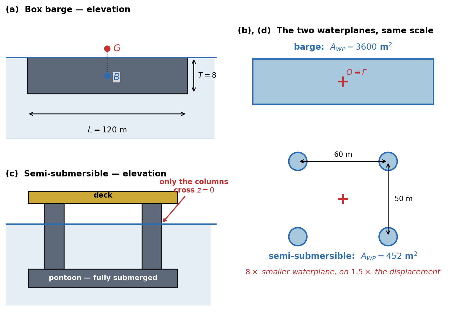
The first is a rectangular box barge, \(L = 120\) m, \(B = 30\) m, floating at an even-keel draft \(T = 8\) m with its centre of gravity \(KG = 10\) m above the keel. Its waterplane is a full rectangle, so every integral in \(\boldsymbol{C}\) can be done in closed form and checked by hand — which is exactly why it is used here.
The second is a semi-submersible drilling unit of \(45\,000\) t displacement, floating on four circular columns of \(12\) m diameter whose centres sit at \(x = \pm 30\) m and \(y = \pm 25\) m, with the bulk of the buoyancy in submerged pontoons well below the surface. Its waterplane is four small circles and nothing else.
Both float. They respond to the sea in completely different ways, and the whole of that difference is written in \(A_{WP}\).
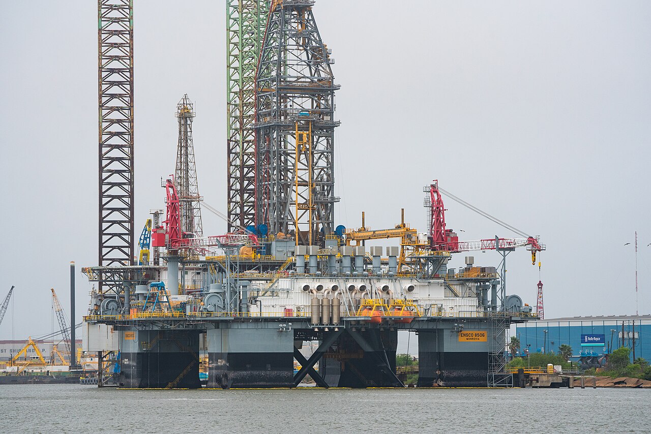
Figure 6.6 sets the two hulls side by side. The elevations show where the buoyancy is; the waterplanes, drawn to a common scale, show where the stiffness comes from — and they are what Problems 1–4 are really about.
The stiffness matrix of a box barge. Take the barge described above, with the BCS origin at midship on the waterline.
- Evaluate \(A_{WP}\), \(\nabla\), the displacement mass \(m\), and the waterplane integrals \(I_x^A\), \(I_y^A\), \(I_{xy}^A\), \(I_{xx}^A\) and \(I_{yy}^A\) about the BCS origin. State which of them vanish and give the geometric reason in each case.
- Obtain \(KB\), \(BM_T\), \(BM_L\) and hence \(GM_T\) and \(GM_L\). Assemble the full \(6\times6\) matrix \(\boldsymbol{C}\).
- \(\boldsymbol{C}\) has three zero rows and three zero columns. Name the degrees of freedom they belong to and explain, from the physical argument of this chapter rather than from the algebra, why a freely floating body has no hydrostatic stiffness in them at all. What consequence does this have for a vessel that must hold station?
- The ratio \(GM_L/GM_T\) for this barge is large. Compute it, and explain which single geometric quantity is responsible for essentially all of it.
- Taking the radii of gyration about \(G\) as \(k_x = 0.35B\) and \(k_y = 0.25L\), and ignoring added mass entirely, estimate the natural periods in heave, roll and pitch. Which of the three will be most in error when added mass is put back, and why?
Moving the origin creates coupling that was never there. The barge of Problem 1 is unchanged in every physical respect, but a designer chooses to place the BCS origin at a convenient structural frame \(12\) m aft of midship instead of at midship. The hull, its draft and its loading are all exactly as before.
- In the new BCS the waterplane still spans the same rectangle, but is no longer centred on the origin. Evaluate \(I_x^A\) and \(I_{xx}^A\) about the new origin, and hence write down the new \(GM_L\) and the new \(\boldsymbol{C}\).
- The matrix now has non-zero entries \(C_{35} = C_{53}\). Give the physical statement each of these two entries makes — one sentence for \(C_{35}\) read as “a pitch produces a heave force”, and one for \(C_{53}\) read as “a heave produces a pitch moment”.
- Express the coupling as the dimensionless ratio \(|C_{35}|/\sqrt{C_{33}C_{55}}\). Is the coupling weak or strong?
- \(GM_L\) came out larger than in Problem 1. A student concludes that the barge has become more stable in pitch simply because the origin was moved. Identify the error, and state what physical quantity has genuinely not changed. Demonstrate it: take the radii of gyration of Problem 1(e), place \(G\) on the same vertical as the midship waterplane centroid at \(KG = 10\) m, and solve the coupled heave–pitch eigenvalue problem \(\det(-\omega^2\boldsymbol{M} + \boldsymbol{C}) = 0\) in both coordinate choices.
- State the one condition on the choice of origin that makes \(C_{35}\) vanish, and explain why designers nevertheless often accept a non-zero \(C_{35}\).
A tank of ballast water that is not where you think it is. The barge of Problem 1 (origin back at midship) is fitted with a rectangular ballast tank \(20\) m long and \(15\) m wide, partially filled with sea water. The tank is deep enough that its free surface stays clear of the top and bottom at all angles considered. The total mass of the barge and its contents, and the position of \(G\), are exactly as in Problem 1 — the ballast has already been counted in both.
- When the barge rolls by a small angle, the water in the tank runs to the low side. Explain, using the same two-part argument this chapter uses for the hull itself (\(G\)–\(B\) separation plus a waterplane integral), why this produces a moment that reduces the restoring moment rather than adding to it.
- The loss of transverse metacentric height caused by a free liquid surface is \(\delta GM_T = i_t/\nabla\), where \(i_t\) is the second moment of the tank’s free surface area about its own centreline. Evaluate \(\delta GM_T\) and the corrected \(GM_T\) and \(C_{44}\).
- Compute the roll natural period before and after, using \(k_x = 0.35B\) and a roll added inertia of \(0.20\,I_{44}\). By what percentage does the period change, and in which direction?
- Suppose the tank is \(6\) m deep and half full, so it holds roughly \(3\%\) of the barge’s displacement. Show, from the form of \(i_t\), why the amount of water is not what governs the loss at all, and state the single tank dimension a designer should attack first. Quantify the benefit of splitting the tank in two with a centreline bulkhead.
- Does \(\delta GM_T\) depend on how much water is in the tank? Does it depend on the density of the liquid in it? Answer both, and identify the practical measure used aboard ship to control this effect.
Why a drilling rig is built on four thin legs. Take the semi-submersible described above: displacement \(45\,000\) t, four circular columns of diameter \(D = 12\) m piercing the free surface with centres at \(x = \pm 30\) m, \(y = \pm 25\) m, and all remaining buoyancy in fully submerged pontoons. The heave added mass is large for such a form; take \(A_{33} = 1.5\,m\).
- Evaluate \(A_{WP}\) and \(C_{33}\), and compare \(A_{WP}\) with that of the barge of Problem 1. Explain why the submerged pontoons, which carry most of the buoyancy, contribute nothing to \(A_{WP}\).
- Compute the heave natural period, first ignoring added mass and then with \(A_{33} = 1.5\,m\). Do the same for the barge of Problem 1, using \(A_{33} = 1.0\,m\) there.
- Ocean waves that carry significant energy have periods roughly in the band \(5\)–\(20\) s. Place all four heave periods from part (b) on that band and state, in one sentence for each vessel, what the design achieves.
- Evaluate \(I_{xx}^A\) and \(I_{yy}^A\) for the four-column waterplane, treating each column both as a point area at its centre and with its own \(\pi D^4/64\), and comment on the size of the self term. Hence obtain \(BM_T\) and \(BM_L\).
- The rig’s designers made \(A_{WP}\) as small as they dared, but not smaller. Give the two distinct penalties of shrinking the columns further — one that appears in \(\boldsymbol{C}\), and one that concerns what happens when a load is added to the deck.
Throwing away viscosity, and knowing when you may not. This chapter justifies an inviscid fluid by the estimate \(F_v/F_p \sim \nu^{1/2}\omega^{3/2}/g\), obtained with a boundary layer thickness \(\delta \sim \sqrt{\nu/\omega}\).
- A \(200\) m ship radiates waves of its own length in deep water. Using the deep water dispersion relation \(\omega = \sqrt{gk}\) with \(k = 2\pi/\lambda\) and \(\lambda = L\), find \(\omega\), then \(\delta\) and the ratio \(F_v/F_p\). Repeat for a \(2\) m model of the same hull tested at the same \(\lambda/L\).
- The ratio grows as \(\omega^{3/2}\), and the model runs at a higher frequency. By what factor does \(F_v/F_p\) increase from ship to model? Is the inviscid assumption still safe for the model?
- Evaluate \(\delta\) for both. Compare each with its hull length and comment on the picture of the flow this justifies.
- Radiation damping and viscous damping are physically unrelated, yet both remove energy from a rolling ship. For the \(200\) m ship in roll, state which of the two dominates and why the argument of parts (a)–(c) does not settle the question. Name the geometric feature commonly fitted to exploit this.
- A colleague proposes to check a potential flow code by setting \(\nu = 0\) in a viscous CFD solver and expecting the radiation damping \(B_{33}\) to fall to zero. Explain what would actually happen and why.
What linearization actually costs. This problem is about the boundary value problem summarised in the interactive anatomy of the boundary value problem, and needs no arithmetic beyond part (d).
- Of the six statements that make up the problem — Laplace’s equation, the kinematic and dynamic free surface conditions, the bottom condition, the radiation condition and the body condition — state which are exactly linear before any approximation is made, and which are not. For each nonlinear one, point to the specific term responsible.
- A student says “we linearize the governing equation to make the problem solvable.” Correct the statement precisely, and say where all of the approximation in this chapter actually lives.
- Linearization does two distinct things to the free surface condition. One is dropping terms; the other is a change of where the condition is imposed. State both, and explain why the second is what makes the problem solvable at all, given that the free surface elevation is itself an unknown.
- A barge of \(8\) m draft oscillates in heave with amplitude \(0.4\) m in waves of \(2\) m amplitude and \(80\) m length. Estimate the wave slope \(\epsilon = ka\) and the ratio (motion amplitude)/(draft). On this evidence, is first order theory reasonable? Now repeat for a storm with \(8\) m amplitude waves of the same length and a \(2.0\) m heave, and comment.
- Once linearized, the problem is split into six sub-problems, one per degree of freedom, each solved one frequency at a time. Name the two distinct principles that license these two splittings, and state what would be lost if either failed.
Problems 7–10 leave hydrostatics behind and deal with the radiation problem. Figure 6.7 shows the two things they turn on: where radiation damping physically comes from, and why the natural frequency of Problem 7 is a fixed point rather than a formula.
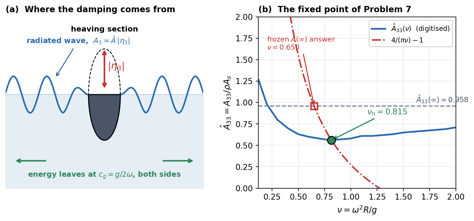
A natural frequency you cannot solve for in one step. A long horizontal circular cylinder of radius \(R = 10\) m floats with its axis in the calm free surface and heaves in deep water. All quantities are per unit length: the mass is \(m' = \rho A_s\) with \(A_s = \tfrac12\pi R^2\), and the heave stiffness is \(K' = \rho g (2R)\), the waterplane breadth being the diameter. This is the section of the radiation simulation above. Its non-dimensional added mass \(\hat{A}_{33} = A_{33}/(\rho A_s)\), digitised from Fig. 3.6 of Faltinsen (1990) as a function of \(\nu = \omega^2R/g\), is the data plotted by that simulator:
\(\nu\) 0.4 0.5 0.6 0.7 0.8 0.9 1.0 1.2 \(\hat{A}_{33}\) 0.700 0.630 0.600 0.580 0.560 0.570 0.580 0.610 Interpolate linearly between the tabulated points. The infinite frequency value is \(\hat{A}_{33}(\infty) = 0.958\).
- Verify that \(m'\) and \(K'\) give \(\omega_n^2 = K'/(m' + A_{33})\), and show that in non-dimensional form the condition becomes \(\nu\left(1 + \hat{A}_{33}(\nu)\right) = 4/\pi\), independent of \(R\). Explain what that independence means physically.
- Solve the fixed point iteration \(\nu_{i+1} = (4/\pi)/(1 + \hat{A}_{33}(\nu_i))\) starting from \(\nu_0 = 0.8\). Tabulate the first five iterates and give the converged \(\nu_n\), \(\omega_n\) and \(T_n\).
- Now do it the naive way: freeze the added mass at its infinite frequency value \(\hat{A}_{33}(\infty) = 0.958\) and solve in one step. Report the resulting \(T_n\) and the percentage error against part (b).
- Repeat parts (b) and (c) for \(R = 4\) m and \(R = 16\) m. Confirm that the percentage error is the same at all three radii, and explain why that had to be so.
- A designer asks why \(\boldsymbol{A}(\omega)\) cannot simply be replaced by a single constant “entrained mass of water”, as an undergraduate textbook suggests. Answer using your numbers, and state the one circumstance in which a constant added mass is legitimate.
Damping without friction. The same cylinder, \(R = 10\) m, now heaves at \(\omega = 0.94\) rad/s with amplitude \(|\eta_3| = 1.5\) m in deep water. At this frequency \(\nu = \omega^2R/g \simeq 0.90\), a tabulated point of the digitised data of Faltinsen (1990), where \(\hat{B}_{33} = 0.420\), where \(B_{33} = \hat{B}_{33}\,\rho\,\omega A_s\) and \(A_s = \tfrac12\pi R^2\). The fluid is inviscid throughout.
- Evaluate \(\nu\), \(B_{33}\), and the radiated wave amplitude ratio \(\bar{A} = A_3/|\eta_3|\) from the energy relation \(\eqref{eq-faltinsen-326}\), \(\bar{A} = \nu\sqrt{\pi\hat{B}_{33}/2}\). What is the height of the radiated wave?
- Compute the average power dissipated per unit length, \(\bar{P} = \tfrac12 B_{33}\omega^2|\eta_3|^2\), and the energy removed per cycle.
- Verify that answer independently: a deep water wave of amplitude \(A_3\) carries mean energy \(\tfrac12\rho g A_3^2\) per unit area, transported at the group velocity \(c_g = g/2\omega\). Two wave trains leave the cylinder, one to each side. Show that the power they carry equals \(\bar{P}\), and state what this identity proves about the origin of \(B_{33}\).
- The energy is leaving the body. Where does it go, and in what sense is it “lost”? Contrast this carefully with the dashpot of Chapter 2.
- From \(\eqref{eq-faltinsen-326}\), argue that \(B_{33} \ge 0\) always, whereas \(A_{33}\) carries no such guarantee and is in fact negative for some sections. Why does the argument constrain one and not the other?
Why the time domain needs a convolution. A single degree of freedom (heave) model of a floating body has, per unit length, \(m + A_{33}(\infty) = 4.00\times10^{5}\) kg/m and \(C_{33} = 2.00\times10^{5}\) N/m per m. Its radiation damping is well represented over all frequencies by \[B_{33}(\omega) = B_0\frac{\omega^2}{\omega^2 + p^2}, \qquad B_0 = 2.00\times10^{5}\ \text{kg/(m·s)}, \quad p = 0.50\ \text{rad/s}\]
- State \(B_{33}(0)\) and \(B_{33}(\infty)\), and give the physical meaning of each limit for a heaving body.
- Using \(\boldsymbol{K}(\tau) = \frac{2}{\pi}\int_0^\infty\left(\boldsymbol{B}(\omega) - \boldsymbol{B}(\infty)\right)\cos(\omega\tau)\,d\omega\) and the standard integral \(\int_0^\infty \frac{\cos\omega\tau}{\omega^2+p^2}d\omega = \frac{\pi}{2p}e^{-p\tau}\), show that \(K(\tau) = -B_0\,p\,e^{-p\tau}\). Evaluate \(K(0)\) and the memory time over which \(K\) decays to \(1\%\) of that value.
- Recover \(A_{33}(\omega) - A_{33}(\infty)\) from \(K(\tau)\) using \(A(\omega) = A(\infty) - \frac{1}{\omega}\int_0^\infty K(\tau)\sin(\omega\tau)d\tau\), and evaluate it at \(\omega = 0.3\), \(0.8\) and \(1.5\) rad/s. Confirm your result numerically.
- Write out the Cummins equation for this body in free decay, and explain in one sentence what the convolution term is physically doing that \(\boldsymbol{B}(\infty)\{\dot\xi\}\) alone cannot.
- A student proposes to skip the convolution and simply use \(-A_{33}(\omega_n)\ddot\xi - B_{33}(\omega_n)\dot\xi\) with the coefficients evaluated once at the natural frequency. State the one situation in which this is exactly right, and one realistic situation in which it fails badly.
Programming Problem: A heave decay test in the time domain. Simulate the free decay of the body of Problem 9, released from rest at \(\xi_3(0) = 1.0\) m with \(\dot\xi_3(0) = 0\) and no motion before \(t = 0\). Because \(K(\tau) = -B_0pe^{-p\tau}\) is a single decaying exponential, the convolution can be replaced exactly by one extra state variable: define \[\mu(t) = \int_{-\infty}^{t}K(t-\tau)\dot\xi_3(\tau)\,d\tau \qquad\Longrightarrow\qquad \dot\mu = -p\,\mu + K(0)\,\dot\xi_3\]
- Verify that state space form of the convolution by differentiating the integral, and write the three first-order equations to be integrated.
- Integrate to \(t = 60\) s and report the first four peak times. Estimate the damped period and the logarithmic decrement from the peaks, and say why the very first interval — from the release at \(t=0\) to the first peak — should be excluded from that estimate.
- Because the memory state \(\mu\) is a third state variable, this system is third order, not second, and its damped period can be obtained exactly from the roots of the characteristic cubic. Derive that cubic, find its roots, and compare the exact damped period with three estimates: the simulation of part (b), the frequency domain fixed point \(-\omega^2\left(m + A_{33}(\omega)\right) + C_{33} = 0\) using \(A_{33}(\omega)\) from Problem 9(c), and the crude \(A_{33}(\infty)\) value. Rank them, and say what the residual error of the fixed point estimate is telling you.
- Re-run with the convolution deleted (that is, with \(\mu \equiv 0\), keeping \(B_{33}(\infty)\)). Report the period and the decrement, and explain the direction of both errors.
- The retardation function here is negative for all \(\tau\). Explain what that means for the sign of the memory force during a decay, and reconcile it with the requirement that the total damping still removes energy.
Answer Key
Problem 1 — The stiffness matrix of a box barge
(a) With the origin at the centroid of a symmetric waterplane, the first moments and the product moment vanish.
Basic quantities. \(A_{WP} = LB = 3600\) m\(^2\), \(\nabla = LBT = 28800\) m\(^3\), \(m = \rho\nabla = 2.9520 \times 10^{7}\) kg (\(29.52\times10^{3}\) t).
Second moments. \(I_{xx}^A = BL^3/12 = 4.3200 \times 10^{6}\) m\(^4\) and \(I_{yy}^A = LB^3/12 = 2.7000 \times 10^{5}\) m\(^4\).
Those that vanish. \(I_x^A = \iint x\,dA = 0\) and \(I_y^A = \iint y\,dA = 0\), because the origin is at the waterplane centroid (the centre of flotation \(F\)), and first moments about a centroid are zero by definition. \(I_{xy}^A = \iint xy\,dA = 0\), because the waterplane is symmetric about \(y = 0\): every element at \(+y\) has a twin at \(-y\).
(b) Only heave, roll and pitch have stiffness, and here they are uncoupled.
Metacentric heights. \(KB = T/2 = 4.00\) m, \(BM_T = I_{yy}^A/\nabla = 9.3750\) m, \(BM_L = I_{xx}^A/\nabla = 150.00\) m, so \(GM_T = 4.00 + 9.3750 - 10.00 = 3.3750\) m and \(GM_L = 144.00\) m.
Matrix (N/m, N and N·m): \[\boldsymbol{C} = \begin{bmatrix} 0 & 0 & 0 & 0 & 0 & 0 \\ 0 & 0 & 0 & 0 & 0 & 0 \\ 0 & 0 & 3.620\!\times\!10^{7} & 0 & 0 & 0 \\ 0 & 0 & 0 & 9.774\!\times\!10^{8} & 0 & 0 \\ 0 & 0 & 0 & 0 & 4.170\!\times\!10^{10} & 0 \\ 0 & 0 & 0 & 0 & 0 & 0 \end{bmatrix}\]
Why uncoupled. The only non-zero entries are \((3,3)\), \((4,4)\) and \((5,5)\) because \(I_x^A\), \(I_y^A\) and \(I_{xy}^A\) all vanished in part (a).
(c) Surge, sway and yaw move the hull horizontally, change nothing the water can feel, and so have no restoring force at all.
Why. A horizontal displacement leaves the underwater volume, the buoyancy and its line of action unchanged, with \(G\) and \(B\) still on one vertical: there is nothing to restore.
Consequence. A floating body is neutrally stable in these modes and drifts and yaws under any residual force. Station keeping must be supplied by moorings or by thrusters under dynamic positioning.
(d) The ratio comes from the length-to-beam ratio, which enters the waterplane integral cubed.
Value. \(GM_L/GM_T = 42.7\).
Cause. Both \(GM\)s share \(KB - KG = -6.00\) m and differ only through \(BM = I^A/\nabla\). With \(I_{xx}^A = BL^3/12\) and \(I_{yy}^A = LB^3/12\), \(BM_L/BM_T = (L/B)^2 = 16\).
Why the \(GM\) ratio is larger still. The common negative term removes the same \(6.00\) m from both, a large fraction of the small transverse value but almost nothing of the longitudinal one. A ship is far stiffer in pitch than in roll, which is why roll is the troublesome mode.
(e) Heave will be the most in error, because its added mass is comparable with the displacement.
Inertias. \(k_x = 10.50\) m and \(k_y = 30.00\) m give \(I_{44} = 3.2546 \times 10^{9}\) and \(I_{55} = 2.6568 \times 10^{10}\) kg·m\(^2\).
Periods without added mass. \(T_3 = 2\pi\sqrt{m/C_{33}} = 5.67\) s, \(T_4 = 2\pi\sqrt{I_{44}/C_{44}} = 11.47\) s, \(T_5 = 5.02\) s.
Error. For a beamy, flat-bottomed hull \(A_{33} \sim m\), so \(T_3\) can be out by \(30\)–\(40\%\). Roll and pitch added inertias are typically only \(10\)–\(20\%\) of the rigid body values, because rotation sets far less water in motion. Problem 4 puts numbers to this.
Problem 2 — Moving the origin creates coupling that was never there
(a) An origin away from the centre of flotation gives a non-zero first moment and a larger second moment.
First moment. The centroid is now at \(x_F = +12\) m, so \(I_x^A = A_{WP}x_F = 4.3200 \times 10^{4}\) m\(^3\).
Second moment (parallel axes for areas). \(I_{xx}^A = BL^3/12 + A_{WP}x_F^2 = 4.8384 \times 10^{6}\) m\(^4\), so \(BM_L = 168.00\) m and \(GM_L = 162.00\) m.
Matrix. One symmetric pair appears, \(C_{35} = C_{53} = -\rho gI_x^A = -4.3439 \times 10^{8}\) N: \[\boldsymbol{C} = \begin{bmatrix} 0 & 0 & 0 & 0 & 0 & 0 \\ 0 & 0 & 0 & 0 & 0 & 0 \\ 0 & 0 & 3.620\!\times\!10^{7} & 0 & -4.344\!\times\!10^{8} & 0 \\ 0 & 0 & 0 & 9.774\!\times\!10^{8} & 0 & 0 \\ 0 & 0 & -4.344\!\times\!10^{8} & 0 & 4.691\!\times\!10^{10} & 0 \\ 0 & 0 & 0 & 0 & 0 & 0 \end{bmatrix}\]
(b) Off the centre of flotation, a pitch changes the displaced volume and a heave creates a moment.
Sign convention. With \(x\) forward and \(z\) up, positive pitch carries the bow down: the local draft changes by \(x\,\xi_5\).
\(C_{35}\): a pitch produces a heave force. The pitch immerses everything forward of the origin and lifts everything aft. About \(F\) the two wedges would cancel; but the origin is \(12\) m aft of \(F\), so the immersing part is larger and the body gains buoyancy, a net upward force, without heaving: \(\tau_{hst,3} = -C_{35}\xi_5 = +\rho gI_x^A\xi_5 > 0\).
\(C_{53}\): a heave produces a pitch moment. A downward heave (\(\xi_3 < 0\)) adds a uniform layer of buoyancy acting through \(F\), \(12\) m forward of the origin: a bow-up (negative) pitch moment, \(\tau_{hst,5} = -C_{53}\xi_3 = \rho gI_x^A\xi_3 < 0\), without pitching.
Why equal. Both are the integral \(\rho g\iint x\,dA\); the symmetry of \(\boldsymbol{C}\) says the restoring forces come from a potential energy.
(c) The coupling is strong.
Ratio. \(|C_{35}|/\sqrt{C_{33}C_{55}} = 0.3333\), about \(33\%\).
Meaning. A heave decay test analysed as an independent single degree of freedom would show a visible pitch oscillation.
(d) \(GM_L\) depends on the point moments are taken about; the natural frequencies do not.
The error. Treating \(GM_L\) as a property of the vessel alone. Hull, displacement, loading and water are unchanged, and the barge is no more stable. The larger \(GM_L\) is offset by the new \(C_{35}\) and by the matching \(-mx_G\) terms in the mass matrix about the shifted origin.
The invariant. The natural frequencies of the coupled system. Solving \(\det(-\omega^2\boldsymbol{M} + \boldsymbol{C}) = 0\) in the heave–pitch plane: \[\omega_n = (1.107362,\ 1.250062)\ \text{rad/s at midship},\] \[\omega_n = (1.107362,\ 1.250062)\ \text{rad/s at the shifted origin},\] identical to every digit (periods \(5.6740\) s and \(5.0263\) s).
A test for any hydrostatics code. Change the origin, and the predicted periods must not move (figure below).

(e) \(C_{35}\) vanishes only with the origin on the station of the centre of flotation, which moves with the loading.
Condition. \(C_{35} = -\rho g\iint x\,dA = 0\) if and only if \(x_F = 0\).
Why designers accept \(C_{35} \ne 0\). \(F\) migrates with draft and trim, so an origin locked to it would make all geometry, sensor positions and mass properties condition dependent. A fixed structural origin buys constant geometry, and since \(\boldsymbol{C}\) is assembled numerically anyway, the off-diagonal terms cost nothing.
Problem 3 — A tank of ballast water that is not where you think it is
(a) The tank’s water runs to the low side and moves \(G\) that way, which heels the vessel further: the hull’s own argument with the sign reversed.
The wedge. The tank’s free surface tips with the barge, transferring a wedge of water from the high side to the low side. For the hull this moves \(B\) to the low side and rights the vessel; for the tank it moves \(G\) to the low side and heels it.
The \(G\)–\(B\) lever. With \(G\) shifted horizontally, the lever between weight and buoyancy shrinks by exactly that shift.
Result. The moment is proportional to the tank’s own waterplane integral \(\iint_{A_t}y^2\,dA = i_t\) and opposes the restoring moment, so it is subtracted.
(b) The free surface removes about a third of the stability margin.
Values. \(i_t = l_tb_t^3/12 = 20\times15^3/12 = 5625.0\) m\(^4\), \(\delta GM_T = i_t/\nabla = 5625.0/28800 = 0.1953\) m, and \(GM_T = 3.3750 - 0.1953 = 3.1797\) m: a loss of \(5.8\%\).
Stiffness. \(C_{44}\) falls from \(9.7737 \times 10^{8}\) to \(9.2081 \times 10^{8}\) N·m/rad.
(c) The roll period lengthens, a classical warning sign of lost stability.
Inertia. Rigid body \(3.2546 \times 10^{9}\) kg·m\(^2\); with \(20\%\) added, \(I_{44} + A_{44} = 3.9055 \times 10^{9}\) kg·m\(^2\).
Periods. \(T_4 = 12.560\) s before, \(12.940\) s after: \(3.03\%\) longer, because stiffness fell while inertia did not, and \(T \propto 1/\sqrt{C_{44}}\).
(d) The loss depends on the shape of the free surface, not on the amount of water; the breadth, cubed, is what to attack.
Form. \(\delta GM_T = l_tb_t^3/(12\nabla)\) contains no mass and no density of the contents: a shallow puddle across a wide tank is as damaging as a deep one.
Centreline bulkhead. Same area, volume and mass, but two surfaces of breadth \(b_t/2\): \(i_t \to 2\,l_t(b_t/2)^3/12 = 1406.2\) m\(^4\), exactly \(1/4\) of \(5625.0\) m\(^4\), so \(\delta GM_T\) falls from \(0.1953\) m to \(0.0488\) m.
Lesson. One bulkhead buys back three quarters of the loss, which is why tanks are built long and narrow (figure below).

(e) Not on the amount; yes on the density; and the cure is to keep tanks full or empty.
Amount. No: a tank one tenth full and one tenth from full give the same loss, as long as the surface spans the tank. It vanishes only when empty or pressed full.
Density. Yes: the exact loss is \(\rho_ti_t/(\rho\nabla)\), so fuel oil (\(\rho_t \approx 0.85\rho\)) is about \(15\%\) less damaging than sea water; part (b) assumed sea water in the tank.
Practice. Keep tanks pressed full or empty, minimise the number of slack tanks, and subdivide those that must be slack.
Problem 4 — Why a drilling rig is built on four thin legs
(a) Buoyancy comes from volume, stiffness from waterplane area; the semi-submersible separates the two.
Values. Each column cuts a circle of \(\pi D^2/4 = 113.10\) m\(^2\), so \(A_{WP} = 452.4\) m\(^2\) and \(C_{33} = \rho gA_{WP} = 4.5489 \times 10^{6}\) N/m.
Against the barge. \(A_{WP} = 3600\) m\(^2\), 8.0 times larger, on a displacement only \(0.66\) times as big.
Why the pontoons contribute nothing. \(A_{WP}\) is the body’s intersection with \(z = 0\), which the pontoons never reach. Heave stiffness comes only from the change in displaced volume, \(\Delta\nabla \approx -A_{WP}\xi_3\), and a small vertical move of a fully submerged body changes its displaced volume not at all.
(b) Added mass lengthens both heave periods substantially.
Semi-submersible. \(T_3 = 2\pi\sqrt{m/C_{33}} = 19.8\) s without added mass; with \(A_{33} = 1.5m\) (inertia \(2.5m\)), \(T_3 = 31.2\) s.
Barge. \(5.67\) s without added mass, \(8.02\) s with \(A_{33} = m\).
Size of the correction. \(58\%\) for the rig and \(41\%\) for the barge: in neither case small, which is why \(\boldsymbol{A}(\omega)\) must be computed rather than guessed.
(c) The barge heaves in the wave band; the rig sits far above it and barely responds.
Barge (\(8.0\) s): inside the \(5\)–\(20\) s band, near its most energetic part; it follows the waves.
Rig (\(31\) s): well above the band. Designed to hold a drill string steady, it puts its heave resonance beyond any energetic wave, so it is excited far above resonance: the off-resonance strategy of Chapter 2, achieved by choosing \(A_{WP}\) (figure below).
(d) The column spacing, not the column size, provides the rig’s angular stiffness.
Point-area terms. \(\sum A_cx_i^2 = 4.0715 \times 10^{5}\) m\(^4\) and \(\sum A_cy_i^2 = 2.8274 \times 10^{5}\) m\(^4\).
Self term. \(4\times\pi D^4/64 = 4071.5\) m\(^4\), only \(0.99\%\) of \(I_{xx}^A\) and \(1.42\%\) of \(I_{yy}^A\): negligible, because \(x_i/D = 2.5\) and the separation enters squared.
Metacentric radii. \(I_{xx}^A = 4.1122 \times 10^{5}\) m\(^4\), \(I_{yy}^A = 2.8681 \times 10^{5}\) m\(^4\), \(\nabla = 43902\) m\(^3\), so \(BM_L = 9.37\) m and \(BM_T = 6.53\) m, modest next to the barge’s \(BM_L = 150\) m.
(e) Thinner columns would weaken roll and pitch along with heave, and would make the draft swing with every deck load.
In \(\boldsymbol{C}\). Every non-zero entry is a waterplane integral: \(C_{33} \propto A_{WP}\) and \(C_{44}\), \(C_{55} \propto \rho gI^A\), itself proportional to column area. Shrinking the columns weakens roll and pitch with heave.
Deck load. \(\delta T = W/(\rho gA_{WP})\): a \(1000\) t load sinks the rig \(2.16\) m but the barge only \(0.271\) m, a factor of 8. Columns half as thick would sink it four times further again.
Compromise. The diameter balances a soft rig in waves against a draft that does not change whenever something is craned aboard.

Problem 5 — Throwing away viscosity, and knowing when you may not
(a) For both ship and model, viscous forces are a tiny fraction of the pressure forces.
Ship. \(k = 2\pi/200 = 0.03142\) m\(^{-1}\), \(\omega = \sqrt{gk} = 0.5551\) rad/s (period \(11.3\) s), \(\delta = \sqrt{\nu/\omega} = 1.3421\) mm and \(F_v/F_p \sim \nu^{1/2}\omega^{3/2}/g = 4.22 \times 10^{-5}\).
Model. \(\omega = 5.5515\) rad/s (period \(1.13\) s), \(\delta = 0.4244\) mm and \(F_v/F_p = 1.33 \times 10^{-3}\).
(b) The model is relatively more viscous than the ship, but still safely inviscid for radiation.
Factor. \(\omega_m/\omega_s = \sqrt{L_s/L_m} = 10.0\), so the ratio grows by \((\omega_m/\omega_s)^{3/2} = 31.6\), from \(4.22 \times 10^{-5}\) to \(1.33 \times 10^{-3}\).
Safe? Yes: about one part in a thousand, below any measurement accuracy.
Direction of the trend. Scale effects always make the model the more viscous one, which is why model tests are corrected for viscosity before being scaled up (figure below).

(c) The boundary layer is a skin far thinner than the hull, which is what justifies potential flow.
Ratios. \(\delta/L = 6.71 \times 10^{-6}\) for the ship and \(2.12 \times 10^{-4}\) for the model: about \(1.34\) mm (the thickness of a small coin) and \(0.42\) mm.
Picture. Vorticity stays in that skin, so for the pressure field and the radiated waves the fluid can be treated as irrotational up to the hull, with no-slip replaced by the weaker condition that fluid does not pass through it.
(d) In roll, viscous damping usually dominates, because roll radiates so little that a small viscous effect is large against it.
Why (a)–(c) do not settle it. They compare viscous force with the whole pressure force; what matters for decay is the small damping part of it. A nearly wall-sided hull rolling about an axis near the waterline radiates very weakly, so \(B_{44}\) from potential theory is very small.
The real mechanism. Not thin-boundary-layer friction but flow separation and eddy shedding at the bilges, which the \(\delta \sim \sqrt{\nu/\omega}\) picture does not describe.
The feature. The bilge keel, a fin along the turn of the bilge that forces separation and can double or triple the roll damping. Roll damping is therefore always added from experiment.
(e) \(B_{33}\) would barely change: radiation damping is wave energy leaving, not friction.
What happens. An inviscid solver still makes waves. Setting \(\nu = 0\) removes the boundary layer, not the free surface, and \(B_{33}\) is fixed by the amplitude of the radiated wave \(\eqref{eq-faltinsen-326}\).
How to make it vanish. Remove the free surface: oscillate the body deep underwater, where it radiates nothing, the damping is zero and the added mass survives.
Problem 6 — What linearization actually costs
(a) The interior equation, the bottom and the radiation condition are already linear; the free surface and body conditions are not.
Exactly linear. Laplace’s equation \(\nabla^2\varphi = 0\), the bottom condition \(\partial\varphi/\partial z = 0\) on \(z = -h\), and the radiation condition at \(S_\infty\).
Kinematic free surface condition. The products \(\frac{\partial\varphi}{\partial x}\frac{\partial\eta}{\partial x} + \frac{\partial\varphi}{\partial y}\frac{\partial\eta}{\partial y}\), and being imposed on the unknown surface \(z = \eta(x, y, t)\).
Dynamic free surface condition. The quadratic \(\tfrac12|\nabla\varphi|^2\), again on \(z = \eta\).
Body condition. Applied on the instantaneous wetted surface \(S_B(t)\), whose position depends on the motion being sought.
(b) Laplace’s equation is never linearised; all of the approximation is in the boundary conditions.
Correction. Every order of the perturbation series satisfies the same \(\nabla^2\varphi^{(n)} = 0\). The approximation lives in the two free surface conditions and the body condition: the interior is easy and exact; the difficulty is the shape of the region and its edges.
(c) Linearisation drops small terms and, more importantly, moves the conditions onto fixed, known surfaces.
(i) Dropping terms. The products \(\nabla\varphi\cdot\nabla\eta\) and \(\tfrac12|\nabla\varphi|^2\) are of order \(\epsilon^2\) and are discarded.
(ii) Transferring the condition. A Taylor expansion about \(z = 0\) moves the condition from the unknown \(z = \eta\) to the fixed plane \(z = 0\), and the body condition from \(S_B(t)\) to the mean wetted surface \(S_{B0}\).
Why (ii) is decisive. Before it, the problem is a free boundary problem: the domain is part of the answer and cannot even be meshed. After it, the domain is fixed, the boundaries are meshed once, and the problem is an ordinary linear boundary value problem.
(d) First-order theory is fine in the moderate sea and breaks down in the storm.
Moderate sea. \(k = 2\pi/80 = 0.0785\) m\(^{-1}\), \(\epsilon = ka = 0.157\) and \(\xi_3/T = 0.4/8 = 0.050\). The neglected terms are of order \(\epsilon^2 \approx 0.025\), a \(2.5\%\) error: entirely reasonable.
Storm. \(\epsilon = 0.628\) and \(\xi_3/T = 0.250\): neglected terms of order \(0.39\), a \(39\%\) error, comparable with the answer.
Worse still. A slope of \(0.63\) is near breaking, and a \(2\) m heave on an \(8\) m draft moves the wetted surface by a quarter of the draft, so transferring the body condition to \(S_{B0}\) is indefensible. Linear seakeeping is a fair-weather theory.
(e) Superposition splits the problem by mode, Fourier decomposition by frequency; both need linearity.
Superposition licenses \(\varphi^{(1)} = \sum_{k=1}^{6}\tilde\varphi_k^{(1)}\): one hard problem becomes six solvable ones. Without it the modes would interact, and heave plus pitch would need its own solution.
Fourier decomposition (Chapter 3) licenses one frequency at a time. Without it energy would pass between frequencies and \(\boldsymbol{A}(\omega)\), \(\boldsymbol{B}(\omega)\) would not exist as functions of \(\omega\).
Where both fail. At second order, which is where sum- and difference-frequency effects such as slow drift come from.
Problem 7 — A natural frequency you cannot solve for in one step
(a) In non-dimensional form the resonance condition contains no size at all: the resonant \(\nu\) belongs to the shape.
Derivation. Undamped free heave: \(-\omega_n^2(m' + A_{33}(\omega_n)) + K' = 0\). With \(m' = \rho\pi R^2/2\), \(K' = 2\rho gR\) and \(A_{33} = \hat A_{33}\rho\pi R^2/2\): \[\omega_n^2 = \frac{2\rho gR}{\tfrac12\rho\pi R^2\left(1 + \hat A_{33}\right)} = \frac{4g}{\pi R\left(1 + \hat A_{33}\right)},\] \[\nu = \frac{\omega_n^2R}{g} = \frac{4/\pi}{1 + \hat A_{33}(\nu)}.\]
Meaning. All half-immersed circular cylinders resonate at the same \(\omega^2R/g\), so \(\omega_n \propto R^{-1/2}\): geometric similarity fixes the non-dimensional answer, which is why model tests scale.
(b) The added mass must be evaluated at the frequency being sought, so the equation has to be iterated.
Iteration. \[\begin{array}{c|c|c} i & \nu_i & \hat A_{33}(\nu_i) \\ \hline 0 & 0.800000 & 0.560000 \\ 1 & 0.816179 & 0.561618 \\ 2 & 0.815334 & 0.561533 \\ 3 & 0.815378 & 0.561538 \\ 4 & 0.815375 & 0.561538 \\ 5 & 0.815376 & 0.561538 \end{array}\]
Converged. \(\nu_n = 0.8154\); for \(R = 10\) m, \(\omega_n = \sqrt{\nu_ng/R} = 0.8944\) rad/s and \(T_n = 7.025\) s (figure below).

(c) Freezing the added mass at its infinite-frequency value overestimates it and makes the period twelve percent too long.
One step. \(\nu = (4/\pi)/(1 + 0.958) = 0.6503\), so \(T_n = 7.867\) s against \(7.025\) s: \(+12.0\%\).
Why. The true added mass at resonance is only \(\hat A_{33}(0.815) = 0.562\), barely half of \(0.958\). The error is not conservative, just wrong, and twelve percent can move a vessel into or out of the energetic part of a sea.
(d) The radius scales both answers alike, so the percentage error does not depend on it.
Table. \[\begin{array}{c|c|c|c} R\ \text{(m)} & T_n\ \text{exact (s)} & T_n\ \text{frozen (s)} & \text{error} \\ \hline 4 & 4.443 & 4.975 & +11.98\% \\ 10 & 7.025 & 7.867 & +11.98\% \\ 16 & 8.886 & 9.951 & +11.98\% \end{array}\]
Why. Both \(\nu_n\) and \(\nu_{\text{frozen}}\) are pure numbers, and \(T = 2\pi\sqrt{R/(\nu g)}\), so the ratio of periods is \(\sqrt{\nu_n/\nu_{\text{frozen}}}\), a constant. A bigger cylinder does not make the approximation any better.
(e) There is no constant entrained mass: \(\hat A_{33}\) changes with frequency, and is not even monotonic.
Evidence. Within the table \(\hat A_{33}\) falls from \(0.70\) at \(\nu = 0.4\) to \(0.56\) near \(\nu = 0.8\), then rises through \(0.61\) at \(\nu = 1.2\) towards \(0.958\); and for a two-dimensional section it grows without bound as \(\omega \to 0\).
Meaning. \(A_{33}(\omega)\) is the part of the radiated pressure force in phase with acceleration, and the flow behind it changes shape with frequency: the fluid escapes round the section at low frequency, while at high frequency the free surface acts almost like a rigid lid. A constant costs \(12.0\%\) in the period here.
The legitimate case. A body oscillating at one known frequency (or a narrow band): then \(\boldsymbol{A}\) and \(\boldsymbol{B}\) can be evaluated there once, as the frequency domain does. The time domain, with many frequencies at once, cannot, which is why the Cummins equations need a convolution.
Problem 8 — Damping without friction
(a) The heaving cylinder makes a wave about a metre high.
Values. \(A_s = \tfrac12\pi R^2 = 157.08\) m\(^2\), \(\nu = \omega^2R/g = 0.9007\), \(B_{33} = \hat B_{33}\rho\omega A_s = 6.3565 \times 10^{4}\) kg/(m·s).
Wave. \(\bar A = \nu\sqrt{\pi\hat B_{33}/2} = 0.9007\times\sqrt{\pi\times0.42/2} = 0.7316\), so \(A_3 = \bar A|\eta_3| = 1.0974\) m: a wave height of \(2A_3 = 2.19\) m from a \(3\) m heave.
(b) Power and energy per cycle follow from the damping.
Power. \(\bar P = \tfrac12B_{33}\omega^2|\eta_3|^2 = \tfrac12\times6.3565 \times 10^{4}\times0.94^2\times1.5^2 = 6.3187 \times 10^{4}\) W/m.
Per cycle. \(T = 2\pi/\omega = 6.684\) s, so \(\bar PT = 4.2236 \times 10^{5}\) J/m.
(c) The power absorbed by the damping is exactly the power carried away by the two radiated wave trains.
Wave energy. Each train carries \(\tfrac12\rho gA_3^2 = 6.0546 \times 10^{3}\) J/m\(^2\) at \(c_g = g/2\omega = 5.2181\) m/s.
Two trains. \[2\times\tfrac12\rho gA_3^2\,c_g = 6.3187 \times 10^{4}\ \text{W/m},\] against \(\bar P = 6.3187 \times 10^{4}\) W/m: agreement to \(3e-16\), the same number.
What it proves. The work done against \(B_{33}\) is not turned into heat anywhere; it is, to the last joule, the energy leaving in the waves. That is what \(B_{33}\) is.
(d) The energy travels outwards for ever; it is lost only to the body, unlike a dashpot’s energy, which becomes heat.
Where it goes. Outwards as waves, never returning: the radiation condition says exactly that. The body’s mechanical energy falls, so the motion decays as if a dashpot were fitted.
Against the dashpot of Chapter 2. A dashpot is dissipative: it turns ordered energy into heat, with a constant coefficient. Radiation damping is conservative in the fluid as a whole: the energy stays ordered wave energy, merely carried out of view, and because the transport depends on how the body meets the free surface, \(B_{33}\) depends on frequency.
(e) \(B_{33}\) is fixed by a squared wave amplitude, so it cannot be negative; \(A_{33}\) does no work and has no such constraint.
\(B_{33} \ge 0\). Rearranged, \(\eqref{eq-faltinsen-326}\) is \(B_{33} = \rho\left(A_3/|\eta_3|\right)^2g^2/\omega^3\), with every factor positive. A body cannot extract energy from calm water. A negative computed \(B_{jj}\) is always a numerical error (irregular frequencies, poor mesh).
Why not \(A_{33}\). \(B\) is the part of the force in phase with velocity, the only part that does net work per cycle. \(A_{33}\) multiplies acceleration, \(90^\circ\) from velocity, and does zero net work, so energy conservation says nothing about its sign; it is negative for some sections near resonance.
Problem 9 — Why the time domain needs a convolution
(a) A body moved infinitely slowly makes no waves; one shaken infinitely fast meets a free surface that acts like a lid.
Limits. \(B_{33}(0) = 0\) and \(B_{33}(\infty) = B_0 = 2.0000 \times 10^{5}\) kg/(m·s).
Zero frequency. No waves, no radiated energy, no damping.
Infinite frequency. The free surface cannot respond; the damping tends to a constant, which is what makes \(\boldsymbol{B}(\infty)\) worth separating out. (For a real three-dimensional body \(B(\infty) = 0\); the non-zero limit belongs to this fit, and is why \(K\) below is negative.)
(b) The retardation function is a decaying exponential: the fluid forgets the body’s motion within about ten seconds.
Integrand. \(B_{33}(\omega) - B_{33}(\infty) = B_0\left(\frac{\omega^2}{\omega^2 + p^2} - 1\right) = -\frac{B_0p^2}{\omega^2 + p^2}\).
Transform. \[\begin{aligned} K(\tau) &= \frac{2}{\pi}\int_0^\infty\frac{-B_0p^2}{\omega^2 + p^2}\cos\omega\tau\,d\omega \\ &= \frac{2}{\pi}\left(-B_0p^2\right)\frac{\pi}{2p}e^{-p\tau} \\ &= -B_0\,p\,e^{-p\tau}. \end{aligned}\]
Memory. \(K(0) = -B_0p = -1.0000 \times 10^{5}\) kg/(m·s\(^2\)), falling to \(1\%\) at \(\tau = \ln(100)/p = 9.21\) s. That finite memory lets the convolution be truncated in practice.
(c) One function, \(K(\tau)\), carries the whole frequency dependence of both \(A\) and \(B\).
Added mass. With \(\int_0^\infty e^{-p\tau}\sin\omega\tau\,d\tau = \omega/(\omega^2 + p^2)\), \[\begin{aligned} A_{33}(\omega) - A_{33}(\infty) &= -\frac{1}{\omega}\int_0^\infty\left(-B_0pe^{-p\tau}\right)\sin\omega\tau\,d\tau \\ &= \frac{B_0p}{\omega^2 + p^2}. \end{aligned}\]
Check (kg/m): \[\begin{array}{c|c|c} \omega\ \text{(rad/s)} & \text{analytic} & \text{quadrature} \\ \hline 0.3 & 2.9412 \times 10^{5} & 2.9412 \times 10^{5} \\ 0.8 & 1.1236 \times 10^{5} & 1.1236 \times 10^{5} \\ 1.5 & 4.0000 \times 10^{4} & 4.0000 \times 10^{4} \end{array}\]
Meaning. \(A(\omega)\) and \(B(\omega)\) are not independent: given one, the other follows (the Kramers–Kronig relation), which is how the simulator checks its digitised \(\hat A_{33}\) against \(\hat B_{33}\) (figure below).

(d) The convolution is the memory of the free surface: waves radiated a moment ago are still pushing on the hull.
Cummins equation. \[\begin{aligned} &\left(m + A_{33}(\infty)\right)\ddot\xi_3(t) + B_{33}(\infty)\dot\xi_3(t) \\ &\quad + \int_{-\infty}^{t}K(t - \tau)\dot\xi_3(\tau)\,d\tau + C_{33}\xi_3(t) = 0, \end{aligned}\] with \(m + A_{33}(\infty) = 4.0000 \times 10^{5}\) kg/m, \(B_{33}(\infty) = 2.0000 \times 10^{5}\) kg/(m·s), \(C_{33} = 2.0000 \times 10^{5}\) N/m per m and \(K(\tau) = -1.0000 \times 10^{5}\,e^{-0.5\tau}\).
What it does. The force depends on the whole velocity history, not only its present value; \(\boldsymbol{B}(\infty)\{\dot\xi\}\) is instantaneous and memoryless.
(e) Frozen coefficients are exact for steady motion at one frequency and fail for transients.
Exactly right. For a steady sinusoid at that one frequency: \(A(\omega)\) and \(B(\omega)\) there reproduce the convolution term identically. That is the whole frequency-domain method.
Fails badly. For any motion with many frequencies at once: a free decay, a slam, a sudden load, a mooring line parting, or an irregular sea. In a decay test the early cycles contain frequencies at which \(A(\omega_n)\) and \(B(\omega_n)\) are the wrong coefficients, and the predicted decay is visibly wrong (Problem 10).
Problem 10 — A heave decay test in the time domain
(a) An exponential memory needs no stored history: one extra state variable carries it exactly.
Derivation. With \(K(\tau) = K(0)e^{-p\tau}\) and no motion before \(t = 0\), \(\mu(t) = K(0)\int_0^te^{-p(t - \tau)}\dot\xi_3(\tau)\,d\tau\). Differentiating, the upper limit gives \(K(0)\dot\xi_3(t)\) and the exponential gives \(-p\mu\): \(\dot\mu = -p\mu + K(0)\dot\xi_3\).
System. \[\begin{aligned} \dot\xi_3 &= v, \\ \dot v &= \frac{-B_{33}(\infty)v - \mu - C_{33}\xi_3}{m + A_{33}(\infty)}, \\ \dot\mu &= -p\mu + K(0)v, \end{aligned}\] with \(\xi_3(0) = 1\), \(v(0) = \mu(0) = 0\). This is why retardation functions are fitted by sums of exponentials before a time-domain simulation.
(b) The first interval is short because the fluid’s memory starts empty; the settled intervals give the true period.
Peaks at \(t = 0.000,\ 10.799,\ 22.067,\ 33.336\) s, amplitudes 1.0000, 0.3541, 0.0979, 0.0271 m; intervals 10.799, 11.268, 11.269 s.
Why exclude the first. At \(t = 0\), \(\mu = 0\): the convolution needs about the memory time of Problem 9(b) to build up, and the first interval is visibly short.
Settled estimate. \(T_d = 11.269\) s and \(\delta = 1.2854\), so \(\zeta \approx \delta/\sqrt{4\pi^2 + \delta^2} = 0.2004\). Averaging all three intervals would give \(11.112\) s, \(1.4\%\) low (figure below).

(c) The memory makes the system third order, so no single-frequency estimate is exact.
Cubic. With \(\xi_3 = e^{st}\) and \(\mu = K(0)s\xi_3/(s + p)\): \[\begin{aligned} &\left(m + A_{33}(\infty)\right)s^3 + \left[\left(m + A_{33}(\infty)\right)p + B_{33}(\infty)\right]s^2 \\ &\quad + \left[B_{33}(\infty)p + K(0) + C_{33}\right]s + C_{33}\,p = 0. \end{aligned}\]
Roots. A real \(-0.7718\) and the pair \(-0.1141 \pm 0.5576i\): exact \(T_d = 11.2688\) s and \(\delta = 1.2855\), matching the settled simulation to \(0.00\%\).
Ranking. \[\underbrace{11.269}_{\text{exact}} \approx \underbrace{11.269}_{\text{simulated}} > \underbrace{10.731}_{\text{fixed point, damped}} > \underbrace{10.567}_{\text{fixed point}} > \underbrace{8.886}_{A_{33}(\infty)}\]
\(A_{33}(\infty)\) alone is \(21\%\) low: it omits \(1.6569 \times 10^{5}\) kg/m of added mass, over \(41\%\) of the inertia.
The fixed point is still \(4.8\%\) low after the correction \(T_n/\sqrt{1 - \zeta^2}\) (\(\zeta = 0.1742\)). The extra real root at \(s = -0.772\) is a non-oscillatory mode of the fluid’s memory that no mass–spring–damper has: a transient contains a band of frequencies, and only the convolution reproduces it.
(d) Without the convolution the body is modelled too light and too heavily damped.
Values. \(T_d = 9.499\) s (against \(11.269\) s with memory and \(11.269\) s exact) and \(\delta = 2.3748\) (against \(1.2854\)).
Period too short by \(16\%\): deleting the convolution deletes the extra added mass it represents.
Decay too fast by a factor of \(1.85\): \(B_{33}(\infty) = B_0\) then acts at every frequency, whereas at resonance the true \(B_{33}\) is only \(1.1716 \times 10^{5}\) kg/(m·s), \(59\%\) of \(B_0\). Both errors would be reported, and they do not cancel.
(e) A negative \(K\) acts as extra inertia, not as negative damping; only the total damping must be positive, and it is.
Sign. With a negative coefficient the memory force acts in phase with acceleration: additional inertia, \(A_{33}(\omega) > A_{33}(\infty)\) at every finite frequency, as part (c) of Problem 9 found.
Energy. The total damping is \(B_{33}(\omega) = B_{33}(\infty) + \int_0^\infty K(\tau)\cos\omega\tau\,d\tau\); the integral is negative but never exceeds \(B_{33}(\infty) = 2.0000 \times 10^{5}\), so \(B_{33}(\omega) = B_0\omega^2/(\omega^2 + p^2) \ge 0\), vanishing only at \(\omega = 0\). The convolution need not be dissipative by itself; Problem 8(e) guarantees the total is.