After reading this chapter, you should be able to:
Explain how the conservation of linear and angular momenta separate the dynamics of a rigid body into the translational (Newton) and rotational (Euler) equations of motion
Relate the velocity and acceleration of the centre of gravity \(G\) to those of the BCS origin \(O\), and identify the angular and centripetal contributions that arise because the two points are offset by \(\vec{r}_G\)
Express a cross product as a multiplication by a skew symmetric matrix, and use this to identify \(\dot{\boldsymbol{R}}\boldsymbol{R}^T\) as the skew symmetric matrix constructed from the angular velocity
Explain why the acceleration in the BCS is not the time derivative of the BCS velocity, and derive the relation \(\vec{a} = \dot{\vec{v}} + \vec{\omega} \times \vec{v}\) for a non-inertial frame
Derive the translational equations of motion of a rigid body in the BCS, and transform forces and moments between the centre of gravity \(G\) and the BCS origin \(O\)
Define the inertia tensor and its second and cross mass moments of inertia, apply the parallel axes theorem to transfer it between \(G\) and \(O\), and explain why formulating the equations of motion in the BCS keeps the mass properties time invariant
Derive the rotational equations of motion of a rigid body about the BCS origin, and interpret the gyroscopic and \(\vec{r}_G\) coupling terms that appear in them
Expand the Newton-Euler equations into the six scalar equations corresponding to surge, sway, heave, roll, pitch and yaw
Assemble the rigid body mass matrix \(\boldsymbol{M}_{RB}\) and the Coriolis matrix \(\boldsymbol{C}_{RB}(\{v\})\), and identify the coupling terms that vanish when the BCS origin is placed at the centre of gravity
Combine the dynamic equations with the kinematic equations of Chapter 4 into a twelve state model, and solve it to obtain the velocities and pose of a rigid body under a known set of forces and moments
5.1 Motivation
The last chapter saw the derivtion of the kinematics of a rigid body. This related the velocities of the body to the derivatives of the the positions and orientations. However, it did not entail any discussion on what caused the motion. This chapter will describe the motion caused due to the application of external forces and moments on the rigid body.
Motion of any general rigid body is governed by conservation of linear and angular momenta (Newton’s second law of motion). The derivation of the dynamic equations of motion for a rigid body can be separated into two steps:
The application of conservation of linear momemtum yields the translational equations of motion (also known as Newton’s equations for a rigid body). In this step the vehicle is assumed to be a point mass whose mass is assumed to be concentrated at the center of gravity \(G\).
The application of conservation of angular momemtum yields the rotational euations of motion (also known as Euler’s equations for a rigid body). In this step the mass distribution of the rigid body plays a role in the dynamics.
Consider a rigid body that is both translating and rotating as shown in Figure 5.1, whose center of gravity is denoted by \(G\) and the BCS origin is denoted by \(O\). The GCS frame is depicted as \(X_0Y_0Z_0\) with origin at \(O_0\) and the BCS frame is depicted as \(X'Y'Z'\) with origin \(O\). The three unit vectors along GCS are denoted as \((\hat{i}_0, \hat{j}_0, \hat{k}_0)\) and the corresponding unit vectors along BCS are denoted as \((\hat{i}, \hat{j}, \hat{k})\). The position vector from GCS origin to BCS origin expressed in GCS is denoted as shown in \(\eqref{eq-bcs-origin-vec-gcs}\). The position vector from GCS origin to center of gravity \(G\) expressed in GCS is denoted as shown in \(\eqref{eq-cog-vec-gcs}\). Let vector from BCS origin to the center of gravity \(G\) expressed in BCS be denoted as shown in \(\eqref{eq-cog-vec-bcs}\).
Let the velocity and acceleration of the center of gravity \(G\) expressed in GCS and BCS be denoted by \((\vec{v}_{0G}, \vec{a}_{0G})\) and \((\vec{v}_{G}, \vec{a}_{G})\) respectively. Similarly the angular velocity of the body expressed in GCS and BCS be denoted by \((\vec{\omega}_0, \vec{\alpha}_0)\) and \((\vec{\omega}, \vec{\alpha})\) respectively. Let the velocity and acceleration of the BCS origin \(O\) expressed in GCS and BCS be denoted by \((\vec{v}_{0O}, \vec{a}_{0O})\) and \((\vec{v}, \vec{a})\) respectively. Note that from the previous chapter, the vectors \(\vec{v}\) and \(\vec{\omega}\) are denoted as shown in \(\eqref{eq-vel-bcs}\) and \(\eqref{eq-ang-vel-bcs}\) respectively.
It can be seen that the position vector \(\vec{r}_{0G}\) can be expressed as shown in \(\eqref{eq-position-vec-triangle-law}\) where \(\boldsymbol{R}\) is the rotation matrix.
Note that \(\dot{\vec{r}}_G = 0\) as in the BCS frame, the location of center of gravity \(G\) will not vary with time due to the rigid body assumption. The vector \(\vec{r}_G\) can be expressed from \(\eqref{eq-position-vec-triangle-law}\) as shown in \(\eqref{eq-rG-recast}\).
The product \(\dot{\boldsymbol{R}} \boldsymbol{R}^T\) can be evaluated using symbolic python (sympy package) as seen in the code give below and the final expression in summarized in a compact form in \(\eqref{eq-RdotRT-compact-1}\). Note that \(s_1 = \sin(\phi)\), \(c_1 = \cos(\phi)\), \(s_2 = \sin(\theta)\), \(c_2=\cos(\theta)\), \(s_3 = \sin(\psi)\) and \(c_3 = \cos(\psi)\).
Code
import sympy as sp# Define symbols for angles and their time derivativesphi, theta, psi = sp.symbols('phi theta psi', cls=sp.Function)t = sp.symbols('t')phi = phi(t)theta = theta(t)psi = psi(t)# Define derivatives of angles with respect to timephi_dot = sp.diff(phi, t)theta_dot = sp.diff(theta, t)psi_dot = sp.diff(psi, t)# Define trigonometric functionss1, c1 = sp.sin(phi), sp.cos(phi)s2, c2 = sp.sin(theta), sp.cos(theta)s3, c3 = sp.sin(psi), sp.cos(psi)# Define the rotation matrix RR = sp.Matrix([ [c2*c3, -c1*s3 + s1*s2*c3, s1*s3 + c1*s2*c3], [c2*s3, c1*c3 + s1*s2*s3, -s1*c3 + c1*s2*s3], [-s2, s1*c2, c1*c2]])# Compute the time derivative of RR_dot = R.diff(t)# Compute R^TR_T = R.transpose()# Compute R_dot * R_Tresult = R_dot * R_T# Simplify the resultsimplified_result = sp.simplify(result)simplified_result
From the previous chapter it is seen that the angular velocity of the body \(\vec{\omega}\) is related to the Euler rates by \(\eqref{eq-ang-vel-bcs-repeat}\).
The angular velocity of the body expressed in GCS will be given by \(\eqref{eq-ang-vel-gcs}\). Note that the following code has been used to evaluate the final expression shown in \(\eqref{eq-ang-vel-gcs}\).
Code
import sympy as sp# Define symbols for angles and their time derivativesphi, theta, psi = sp.symbols('phi theta psi', cls=sp.Function)t = sp.symbols('t')phi = phi(t)theta = theta(t)psi = psi(t)# Define derivatives of angles with respect to timephi_dot = sp.diff(phi, t)theta_dot = sp.diff(theta, t)psi_dot = sp.diff(psi, t)# Define trigonometric functionss1, c1 = sp.sin(phi), sp.cos(phi)s2, c2 = sp.sin(theta), sp.cos(theta)s3, c3 = sp.sin(psi), sp.cos(psi)# Define the rotation matrix RR = sp.Matrix([ [c2*c3, -c1*s3 + s1*s2*c3, s1*s3 + c1*s2*c3], [c2*s3, c1*c3 + s1*s2*s3, -s1*c3 + c1*s2*s3], [-s2, s1*c2, c1*c2]])# Define angular velocity omega in BCSomega = sp.Matrix([[phi_dot - s2*psi_dot], [c1*theta_dot + s1*c2*psi_dot], [-s1*theta_dot + c1*c2*psi_dot]])# Angular velocity in GCS omega_0omega_0 = R * omega# Simplify the resultsimplified_result = sp.simplify(omega_0)simplified_result
It can be seen that the right hand side of \(\eqref{eq-RdotRT-compact-1}\) is a skew symmetric matrix constructed from \(\vec{\omega}_0\) shown in \(\eqref{eq-ang-vel-gcs}\). Using the property of expressing cross product as a matrix multiplication, \(\eqref{eq-vel-triangle-law-1}\) can be written as shown in \(\eqref{eq-vel-triangle-law-2}\).
Substituting \((\vec{v}_{0G} - \vec{v}_{0O})\) from \(\eqref{eq-vel-triangle-law-2}\) into \(\eqref{eq-acc-triangle-law-1}\) yields \(\eqref{eq-acc-triangle-law-2}\).
Newton’s second law for a point mass can be written as \(\eqref{eq-newtons-2nd-law}\) where \(\vec{F}_{0}\) is the force acting on the body expressed in GCS. \(m\) denotes the mass of the rigid body.
\[\begin{align}
m \vec{a}_{0G} = \vec{F}_{0}
\label{eq-newtons-2nd-law}
\end{align}\]
Sustituting the acceleration of \(G\) expressed in GCS from \(\eqref{eq-acc-triangle-law-2}\) leads to \(\eqref{eq-newtons-eom}\).
Notice that all the quantities in \(\eqref{eq-newtons-eom}\) are expressed in GCS frame. Premultiplying \(\boldsymbol{R}^T\) on both sides of \(\eqref{eq-newtons-eom}\) leads to translational equations of motion expressed in BCS frame as shown in \(\eqref{eq-newtons-eom-1}\).
Note that \(\boldsymbol{R}^T(\vec{\alpha}_0 \times (\vec{r}_{0G} - \vec{r}_{0O})) = \vec{\alpha} \times \vec{r}_{G}\) and \(\boldsymbol{R}^T(\vec{\omega}_0 \times (\vec{\omega}_0 \times (\vec{r}_{0G} - \vec{r}_{0O}))) = \vec{\omega} \times (\vec{\omega} \times \vec{r}_{G})\). Transforming vectors to BCS and taking a cross product is equivalent to taking a cross product of vectors in GCS and transforming the resultant vector to BCS. \(\vec{F} = X \hat{i} + Y \hat{j} + Z \hat{k}\) in \(\eqref{eq-newtons-eom-1}\) represents the force acting of the rigid body expressed in BCS frame.
In BCS \(\vec{a} \neq \dot{\vec{v}}\) as BCS is a non-inertial frame of reference. Differentiation of velocity will yield acceleration only in an inertial frame. Instead \(\vec{a}\) can be expressed in terms of \(\dot{\vec{v}}\) and \(\vec{v}\) as shown in \(\eqref{eq-acc-vel-der-bcs}\).
Substituting \(\eqref{eq-acc-vel-der-bcs}\) into \(\eqref{eq-newtons-eom-1}\) results in the translational equations of motion in the vector form and are shown in \(\eqref{eq-newtons-eom-2}\).
Let the angular momentum of the vessel about the center of gravity \(G\) expressed in GCS be denoted by \(\vec{L}_{0G}\). Let the angular momentum of the vessel about the center of gravity \(G\) expressed in BCS be denoted by \(\vec{L}_G\). Let the external moment on the vessel about the center of gravity \(G\) expressed in GCS be denoted by \(\vec{M}_{0G}\). The conservation of angular momentum for the vessel is shown by \(\eqref{eq-ang-momentum-conservation}\).
It is well known from rigid body mechanics that the angular momentum of the body in BCS \(\vec{L}_{G}\) can be expressed as the product of inertia tensor and the angular velocity as shown in \(\eqref{eq-ang-mom-inertia}\).
\(I_x^G\), \(I_y^G\) and \(I_z^G\) are the second mass moments of inertia. \(I_{xy}^G\), \(I_{xz}^G\), \(I_{yz}^G\), \(I_{yx}^G\), \(I_{zx}^G\) and \(I_{zy}^G\) are cross mass moments of inertia. The terms in the inertia tensor \(\boldsymbol{I}_G\) are defined with respect to a coordinate system that is parallel to the BCS but with its origin at the center of gravity \(G\).
The second mass moment of inertia \(I_x^G\) is defined as shown in \(\eqref{eq-IxG}\) where \(\mu\) represents the mass density of the body and the volume integral is performed over the volume \(V\) of the rigid body. Note that \((x - x_G)\), \((y - y_G)\) and \((z - z_G)\) represent the distance between the elemental volume \(dV\) and the center of gravity of the rigid body along directions parallel to the y and z axes of the BCS respectively. \(I_y^G\) and \(I_z^G\) are also defined in a similar manner.
\[\begin{align}
I_x^G = I_{yy}^G + I_{zz}^G = \iiint_V \mu \left[(y - y_G)^2 + (z - z_G)^2\right] dV
\label{eq-IxG}
\end{align}\]
The cross mass moment of inertia \(I_{xy}^G\) is defined as shown in \(\eqref{eq-IxyG}\). The other terms \(I_{xz}^G\), \(I_{yz}^G\), \(I_{yx}^G\), \(I_{zx}^G\) and \(I_{zy}^G\) are defined in a similar manner.
Note that for a rigid body \(\boldsymbol{I}_G\) is time invariant. The advantage of formulating the equations of motion in BCS is that the mass properties of the body are time invariant. On the other hand, when the equations of motion are formulated in GCS, the inertia tensor would be a time varying quantity.
Substituting \(\eqref{eq-ang-mom-inertia}\) into \(\eqref{eq-ang-momentum-conservation-2}\) results in \(\eqref{eq-rotational-eqn-cog}\).
Let \(\vec{M} = K \hat{i} + M \hat{j} + N \hat{k}\) denote the external moment acting on the vessel about BCS origin \(O\) expressed in BCS. \(\vec{M}\) and \(\vec{M}_{0G}\) are related as shown in \(\eqref{eq-ext-moment}\) where \(\vec{F}\) is the external force acting on the body expressed in BCS.
Some of the terms can be simplified. Taking the first two terms together and applying the properties of vector cross product and expressing cross products as matrix multiplications yeilds \(\eqref{eq-inertia-simplify-1}\) and \(\eqref{eq-inertia-simplify-1a}\) respectively.
Note that \(\boldsymbol{I}_O\) in the last step is the inertia tensor defined with respect to BCS and is related to \(\boldsymbol{I}_G\) through the parallel axes theorem shown in \(\eqref{eq-parallel-axes-theorem}\).
\[\begin{align}
\boldsymbol{I}_O = \boldsymbol{I}_G - m \boldsymbol{S}(\vec{r}_G) \boldsymbol{S}(\vec{r}_G)
\label{eq-parallel-axes-theorem}
\end{align}\]
Similarly, the third and fourth terms of \(\eqref{eq-euler-eom-2}\) can also be simplified using the Jacobi identity for triple cross products as shown in \(\eqref{eq-inertia-simplify-2}\), \(\eqref{eq-inertia-simplify-3}\) and \(\eqref{eq-inertia-simplify-4}\).
Substituting final expressions from \(\eqref{eq-inertia-simplify-1a}\) and \(\eqref{eq-inertia-simplify-4}\) into \(\eqref{eq-euler-eom-2}\) yeilds the rotational equations in the vector form as shown in \(\eqref{eq-euler-eom-3}\).
When expanded, these form six equations, with one corresponding to each degree of freedom and are shown in (\(\ref{eq-eom-expanded-1}\) - \(\ref{eq-eom-expanded-6}\)).
These equations can be represented in a compact matrix form as shown in \(\eqref{eq-eom-matrix-form}\), where \(\boldsymbol{M}_{RB}\) is a \(6 \times 6\) rigid body mass matrix, \(\boldsymbol{C}_{RB}\left(\{\nu\}\right)\) is the \(6 \times 6\) velocity dependent Coriolis matrix and \(\{\tau_{RB}\}\) is the \(6 \times 1\) external force and moment vector.
The rigid body mass matrix \(\boldsymbol{M}_{RB}\) is shown in \(\eqref{eq-mass-matrix}\), where \(\boldsymbol{I}_{3 \times 3}\) is a \(3 \times 3\) identity matrix.
The Coriolis matrix can be parameterized in terms of the mass matrix as shown in \(\eqref{eq-coriolis-mass-param}\), where \(\boldsymbol{0}_{3 \times 3}\) is a \(3 \times 3\) matrix of zeros. Note that \(\boldsymbol{M}_{11} = m\boldsymbol{I}_{3 \times 3}\), \(\boldsymbol{M}_{12} = -\boldsymbol{M}_{21} = -m \boldsymbol{S}(\vec{r}_G)\) and \(\boldsymbol{M}_{22} = \boldsymbol{I}_O\).
Defining a state vector of size \(12 \times 1\) as shown in \(\eqref{eq-state}\), the kinematic and dynamic equations can be expressed together as shown in \(\eqref{eq-kinematics-dynamics}\).
\[\begin{align}
\{x\} = \begin{bmatrix}
u & v & w & p & q & r & x_{0O} & y_{0O} & z_{0O} & \phi & \theta & \psi
\end{bmatrix}^T
\label{eq-state}
\end{align}\]
If the external forces and moments \(\{\tau_{RB}\}\) are known, then the velocities and pose of the body can be calculated by solving the matrix differential equation shown in \(\eqref{eq-kinematics-dynamics}\).
5.5 Linearized Equations of Motion for a Rigid Body
For a ship or an offshore floating platform, the external forces acting on the body are due to the surrounding fluid. In general these hydrodynamic and hydrostatic forces acting on the body are strongly coupled to the motion of the body. This makes it very difficult to analyze the motions of ships and offshore platforms. In order to make the problem tenable the equations of motion are linearized. The linearization is only valid when the motions are small. However, the linearization allows for the principle of superposition. Thus the forces and external moments can be separated into their respective components and the response of the structure can be obtained by calculating the response of the structure to these component forces and moments.
When the amplitude of motions is assumed to be small, the nonlinear terms that involve the product of two or more small quantities can be neglected. In this case the dynamic equations of motion reduce to \(\eqref{eq-eom-matrix-form-linear}\).
The next chapters will rely on the principle of superposition and separate the the total force and moment acting on the body into its components.
5.6 Exercises
Throughout, the BCS is the body frame of Chapter 4 — \(x\) along the bow, \(y\) to port, \(z\) up — with its origin \(O\) at midship, on the centreline, at the loaded waterline. All six equations are written about \(O\), not about \(G\), exactly as in \(\eqref{eq-eom-expanded-1}\)–\(\eqref{eq-eom-expanded-6}\). Use \(g = 9.81\) m/s\(^2\) and \(\rho = 1025\) kg/m\(^3\).
Every problem can be solved with the results of this chapter — the Newton–Euler equations \(\eqref{eq-newtons-eom-final}\) and \(\eqref{eq-euler-eom-final}\), their expanded scalar forms, the mass matrix \(\eqref{eq-mass-matrix}\), the Coriolis parameterization \(\eqref{eq-coriolis-mass-param}\), the parallel axes theorem \(\eqref{eq-parallel-axes-theorem}\), the moment transfer relation \(\eqref{eq-ext-moment}\) and the combined model \(\eqref{eq-kinematics-dynamics}\) — together with the kinematics of Chapter 4. No hydrodynamics is required anywhere: added mass, damping and wave loads are not part of this chapter, and wherever a force or moment acts on the vessel its value is given to you. Where a hydrostatic restoring moment is needed it is supplied as \(\rho g \nabla\, GM\), which you already know.
Several problems ask you to derive a result before using it numerically; the derivation carries most of the marks. The vessel dimensions are representative of a real ship and serve only to give the numbers a realistic scale.
The vessel and the two points these problems refer to
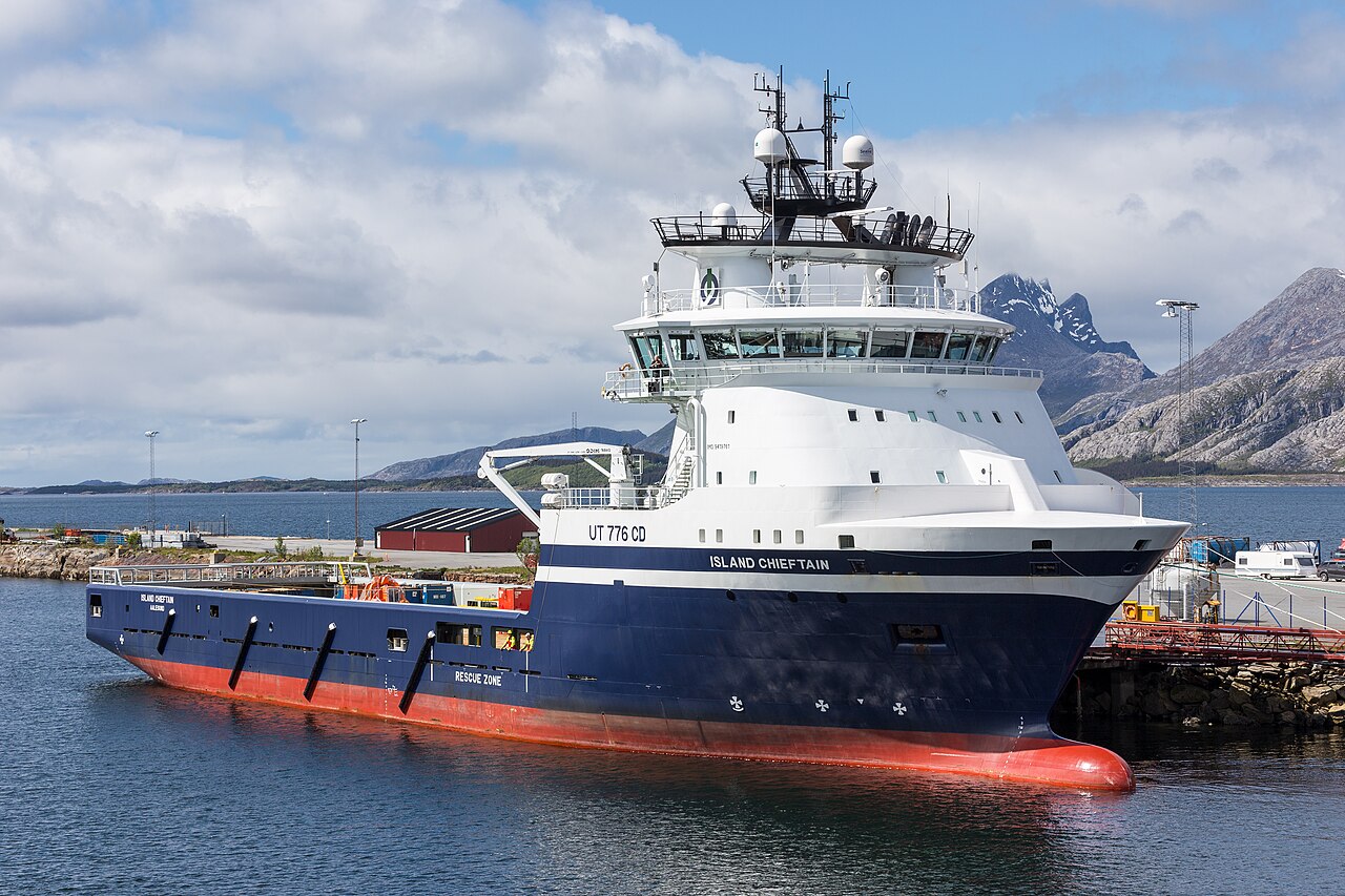
Most of the problems below concern one ship: a platform supply vessel of the kind shown in Figure 5.2, of length \(85\) m, beam \(20\) m and loaded draft \(6.5\) m. It is a useful test case because it is small enough to have a substantial \(\vec{r}_G\) relative to its size, so the coupling terms in \(\eqref{eq-mass-matrix}\) — which vanish only if the origin is placed at \(G\) — are large enough to matter.
Figure 5.2: A platform supply vessel. The open working deck aft, the accommodation forward and the deep skeg give a hull whose centre of gravity is neither at midship nor at the waterline, which is exactly the situation the mass matrix \(\eqref{eq-mass-matrix}\) is written for. Photo: JoachimKohler-HB, CC BY-SA 4.0, via Wikimedia Commons.
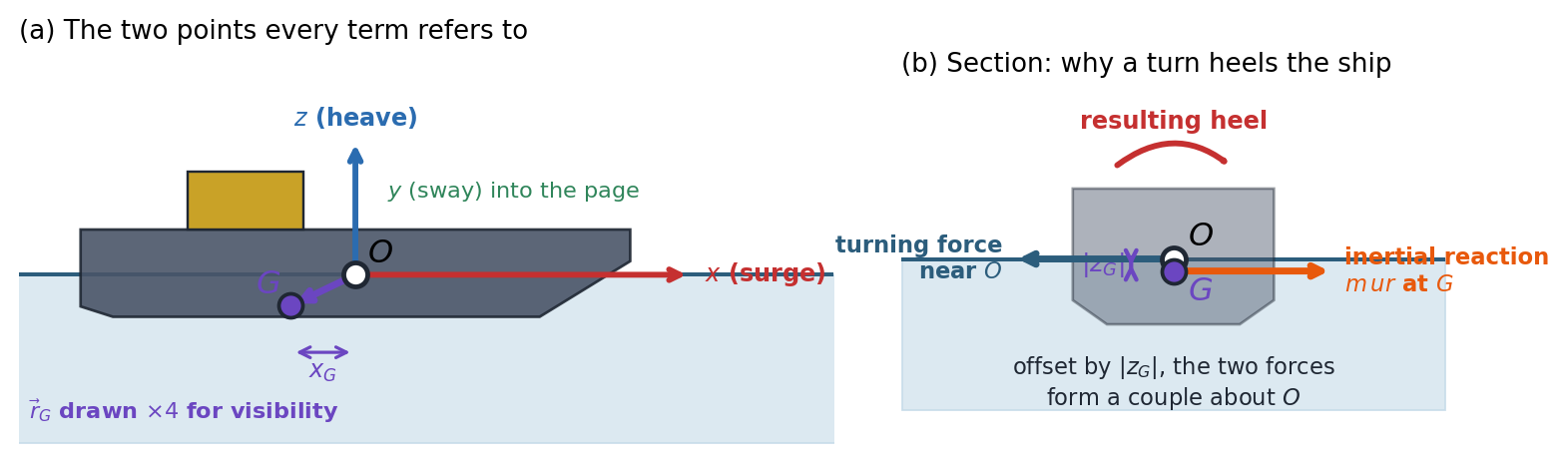
Every term in this chapter’s equations refers to one of two points: the BCS origin \(O\), which is bolted to the hull, and the centre of gravity \(G\), which moves whenever cargo, fuel or ballast moves. Figure 5.3 shows both, together with the geometry behind Problem 3.
Figure 5.3: (a) The BCS origin \(O\) and the centre of gravity \(G\) on the supply vessel, with the offset \(\vec{r}_G\) between them drawn four times its true size so that it can be seen at all. Surge, sway and heave are translations along the body axes; roll, pitch and yaw are rotations about them. (b) The geometry behind Problem 3: the force that turns the ship acts near the waterline while the inertia of the ship reacts at \(G\), and because the two are offset vertically by \(|z_G|\) they form a couple that heels the vessel.
The mass matrix of a supply vessel. The vessel of Figure 5.2 has mass \(m = 6.0\times10^{6}\) kg. Its centre of gravity lies at \(\vec{r}_G = [-2.5,\ 0,\ -1.2]^T\) m in the BCS — a little aft of midship and a little below the waterline. Its radii of gyration about \(G\) are \(k_x = 7.2\) m, \(k_y = 21.0\) m and \(k_z = 21.5\) m, and the hull is port–starboard symmetric so that \(I_{xy}^G = I_{yz}^G = 0\), while \(I_{xz}^G = 2.5\times10^{7}\) kg·m\(^2\).
Write down \(\boldsymbol{I}_G\). Then expand \(-m\boldsymbol{S}(\vec{r}_G)\boldsymbol{S}(\vec{r}_G)\) in \(\eqref{eq-parallel-axes-theorem}\) using the identity \(\boldsymbol{S}(\vec{a})\boldsymbol{S}(\vec{a}) = \vec{a}\vec{a}^T - (\vec{a}\cdot\vec{a})\boldsymbol{I}\), and hence show that the diagonal entries reproduce the familiar scalar results \(I_x^O = I_x^G + m(y_G^2 + z_G^2)\) and so on, while the off-diagonal entry gives \(I_{xz}^O = I_{xz}^G + m x_G z_G\). Evaluate \(\boldsymbol{I}_O\).
Assemble \(\boldsymbol{M}_{RB}\) from \(\eqref{eq-mass-matrix}\) and confirm that it is symmetric. Which property of \(\boldsymbol{S}\) makes the two off-diagonal blocks transposes of one another?
The kinetic energy of the body is \(T = \tfrac{1}{2}\{\nu\}^T\boldsymbol{M}_{RB}\{\nu\}\). Use this to argue that \(\boldsymbol{M}_{RB}\) must be positive definite, and verify it numerically from its eigenvalues. What would a zero eigenvalue mean physically?
Rebuild the matrix with the origin moved to \(G\). Show that both off-diagonal blocks vanish. List the pairs of degrees of freedom that the original off-diagonal terms coupled, and give the size of the largest coupling as a fraction of \(\sqrt{M_{ii}M_{jj}}\) for that pair.
The matrix is plainly simpler at \(G\). Give the reason, already met in Chapter 4, why the equations are nevertheless written about a fixed geometric point.
What an accelerometer on the bridge actually measures. A motion sensor is bolted to the bridge of the vessel of Problem 1 at \(\vec{r}_P = [28,\ 0,\ 16]^T\) m in the BCS. At one instant the vessel has \[\{\nu_1\} = [5.00,\ 0.30,\ -0.20]^T \text{ m/s}, \qquad \{\nu_2\} = [0.080,\ 0.030,\ 0.020]^T \text{ rad/s}\] with rates \(\{\dot{v}_1\} = [0.10,\ -0.05,\ 0.40]^T\) m/s\(^2\) and \(\{\dot{v}_2\} = [0.050,\ -0.020,\ 0.010]^T\) rad/s\(^2\).
Repeat the argument that led to \(\eqref{eq-newtons-eom-1}\), but for an arbitrary material point \(P\) of the body rather than for \(G\), to show that the acceleration of \(P\) expressed in the BCS is \[\vec{a}_P = \dot{\vec{v}} + \vec{\omega}\times\vec{v} + \vec{\alpha}\times\vec{r}_P + \vec{\omega}\times(\vec{\omega}\times\vec{r}_P)\] Identify which terms vanish if the vessel does not rotate, and which vanish if it rotates at a constant rate.
Evaluate \(\vec{a}_P\) and the acceleration \(\vec{a}_O\) of the BCS origin. What fraction of the total does the rotational part contribute?
The vertical channel of this sensor is often read directly as the heave acceleration. Compute the error committed by reading \((\vec{a}_P)_z\) as \(\dot{w}\), and identify which single term is responsible for most of it.
Show that in a steady turn — constant \(u\) and \(r\), everything else zero — only two of the four terms survive. Evaluate the steady lateral acceleration felt on the bridge for \(u = 6.0\) m/s and \(r = 0.050\) rad/s, and express it as a fraction of \(g\).
Where along the hull should the sensor be mounted so that its vertical channel is least contaminated by rotation? Is such a location practical, and what do designers do instead?
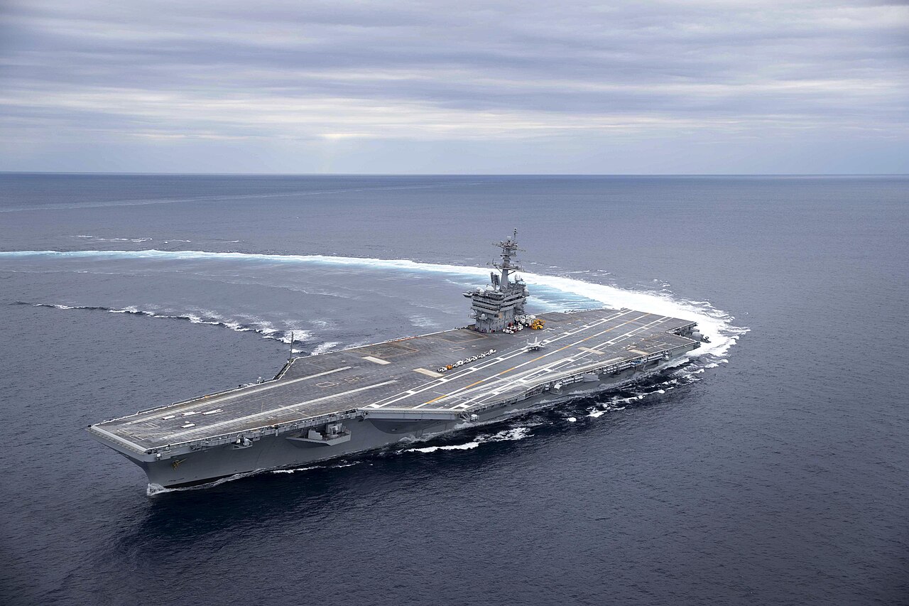
Figure 5.4 shows what this problem is about. The curved wake records the turn; the flight deck, which should be horizontal, is visibly tilted. No wave is doing that — the ship is heeling because of its own inertia, and the roll equation \(\eqref{eq-eom-expanded-4}\) is enough to say by how much.
Figure 5.4: An aircraft carrier during a high-speed turn on sea trials. The wake shows the turning circle and the deck shows the heel that goes with it. Photo: U.S. Navy, public domain, via Wikimedia Commons.
Why a ship heels in a turn. The vessel of Problem 1 is in a steady turn to port: \(u = 6.0\) m/s, \(v = -0.40\) m/s, \(w = 0\), \(p = q = 0\) and \(r = 0.050\) rad/s, every one of them constant. Take \(GM = 1.8\) m.
Impose these conditions on the roll equation \(\eqref{eq-eom-expanded-4}\) and show that it reduces to \(K = r^2 I_{yz} - m z_G u r\), and hence, for a port–starboard symmetric hull, to \(K = -m z_G u r\). Explain in words what each surviving factor represents.
Evaluate \(K\) for this vessel.
In a steady heel the only other roll moment is the hydrostatic righting moment, which for small angles is \(-\rho g \nabla\, GM\, \phi\) with \(\rho\nabla = m\). Equate the two and find the heel angle \(\phi\). Does the vessel lean into the turn or out of it?
The vessel is re-ballasted for a deck cargo so that \(G\) rises to \(z_G = +0.8\) m, above the waterline, with \(GM\) unchanged. Recompute \(\phi\) and explain the reversal in one sentence.
Real ships in a hard turn usually heel outwards, whichever side \(G\) lies. Identify the assumption in this problem that is responsible for the discrepancy, and state what would have to be known to get the sign right in general.
The Coriolis matrix can do no work. This problem establishes a property of \(\eqref{eq-eom-matrix-form}\) that every simulation of it should be tested against.
Using only \(\boldsymbol{S}^T = -\boldsymbol{S}\), show from the parameterization \(\eqref{eq-coriolis-mass-param}\) that \(\boldsymbol{C}_{RB}^T = -\boldsymbol{C}_{RB}\), whatever the velocity.
Hence show that \(\{\nu\}^T\boldsymbol{C}_{RB}(\{\nu\})\{\nu\} = 0\) for every \(\{\nu\}\), and verify numerically for the state of Problem 2.
Differentiate the kinetic energy \(T = \tfrac{1}{2}\{\nu\}^T\boldsymbol{M}_{RB}\{\nu\}\) and use \(\eqref{eq-eom-matrix-form}\) together with part (b) to prove that \(\dot{T} = \{\nu\}^T\{\tau_{RB}\}\). State in one sentence what this says physically.
For the vessel of Problem 1 in the state of Problem 2, with \[\{\tau_{RB}\} = [3.0\times10^{5},\ -8.0\times10^{4},\ 2.0\times10^{5},\ 5.0\times10^{5},\ -1.2\times10^{6},\ 9.0\times10^{5}]^T\] in N and N·m, compute \(\dot{T}\) from the right-hand side, and independently from \(\{\nu\}^T\boldsymbol{M}_{RB}\{\dot{\nu}\}\) with \(\{\dot{\nu}\}\) obtained from \(\eqref{eq-eom-matrix-form}\). Confirm they agree.
A student’s simulator builds \(\boldsymbol{C}_{RB}\) with the sign of its lower-left block flipped. Show that the matrix is then no longer skew-symmetric, and describe the single cheapest numerical test that would expose the error.
A steady turn is not an unaccelerated state. The vessel of Problem 1 holds the steady turn of Problem 3: \(u = 6.0\) m/s, \(v = -0.40\) m/s, \(w = 0\), \(p = q = 0\), \(r = 0.050\) rad/s, all constant.
Write down \(\{\dot{\nu}\}\) for this motion, and say in one sentence why every entry is zero even though the vessel is going round in a circle.
Substitute the state into the six expanded equations \(\eqref{eq-eom-expanded-1}\)–\(\eqref{eq-eom-expanded-6}\) and derive closed-form expressions for \(X\), \(Y\), \(Z\), \(K\), \(M\) and \(N\).
Evaluate all six for this vessel.
Two of the six have a simple interpretation: identify them and give it. Which one would be absent if the origin were at \(G\)?
Resolve the apparent paradox in the title of this problem: how can the required forces be non-zero when every component of \(\{\dot{\nu}\}\) vanishes?
A pure surge force does not produce a pure surge acceleration. The vessel of Problem 1 lies at rest, \(\{\nu\} = \boldsymbol{0}\), when a towline along the body \(x\) axis through the origin suddenly comes taut with \(X = 5.0\times10^{5}\) N. No other force or moment acts.
Show that \(\boldsymbol{C}_{RB}(\{\nu\})\{\nu\} = \boldsymbol{0}\) when \(\{\nu\} = \boldsymbol{0}\), so that \(\eqref{eq-eom-matrix-form}\) reduces to \(\{\dot{\nu}\} = \boldsymbol{M}_{RB}^{-1}\{\tau_{RB}\}\) at this instant.
Compute \(\{\dot{\nu}\}\). Which components besides \(\dot{u}\) are non-zero?
Identify the entries of \(\boldsymbol{M}_{RB}\) responsible, and explain the coupling in words — what is it about the geometry of this ship that makes a horizontal pull start a pitching motion?
Find the pair \((X, M)\) that would produce a pure surge acceleration of the same magnitude as in (b), with every other component of \(\{\dot{\nu}\}\) exactly zero.
If the origin were placed at \(G\), a force through \(G\) along \(x\) would produce pure surge acceleration. Does that mean the coupling in (b) is a mere artefact of a bad choice of origin? Answer carefully, distinguishing the line of action of the force from the choice of reference point.
The same physics from two different origins. A crane on the vessel of Problem 1 holds a load out over the port quarter. The load line applies a force \(\vec{F} = [0,\ -1.80\times10^{5},\ -9.00\times10^{5}]^T\) N at the point \(\vec{r}_A = [-18,\ 9,\ 12]^T\) m in the BCS. The vessel is momentarily at rest.
Compute the moment of this force about \(O\) and about \(G\), and verify the relation \(\eqref{eq-ext-moment}\) numerically.
Using the \(O\)-based mass matrix of Problem 1, assemble \(\{\tau_{RB}\}\) and solve for \(\{\dot{\nu}\}\).
Now repeat the whole calculation with the BCS origin moved to \(G\): build the new mass matrix, express the same physical force and its moment about \(G\), and solve for the accelerations \(\{\dot{\nu}\}^G\).
The two answers are numerically different. Show that they nevertheless describe the same motion, by checking that the angular accelerations are identical and that the linear accelerations satisfy \(\vec{a}_G = \vec{a}_O + \vec{\alpha}\times\vec{r}_G\). (Note that with the vessel at rest, \(\{\dot{\nu}\}\)is the acceleration.)
In part (c) the linear acceleration comes out as exactly \(\vec{F}/m\). Explain why that had to happen, and say which of the two formulations you would prefer when writing a general purpose simulator.
A released subsea module tumbles. A rectangular subsea module of mass \(4.5\times10^{4}\) kg and outside dimensions \(6.0\) m (\(x\)) \(\times\ 3.0\) m (\(y\)) \(\times\ 2.0\) m (\(z\)), of uniform density, is released in mid-water. Place the BCS origin at \(G\) and, for this problem only, neglect every hydrodynamic force and moment, so that the net external force and moment on the module are zero.
Compute the three principal moments of inertia and confirm that they are distinct.
Show that \(\eqref{eq-euler-eom-final}\) reduces for this body to Euler’s equations \(I_x\dot{p} = (I_y - I_z)qr\), \(I_y\dot{q} = (I_z - I_x)rp\), \(I_z\dot{r} = (I_x - I_y)pq\), stating which terms drop out and why.
Linearize about a steady spin of rate \(\Omega\) about each principal axis in turn. Show that two of the three give bounded oscillations and one gives exponential growth, and evaluate the oscillation frequencies and the growth rate for \(\Omega = 1.2\) rad/s.
Integrate the equations numerically from \(\vec{\omega}(0) = [10^{-3},\ 1.2,\ 10^{-3}]^T\) rad/s over \(60\) s and report the times at which the spin about the intermediate axis reverses sign.
About which axis should the module be spun if it must hold its attitude? Comment on what the neglected hydrodynamic moments would do to this picture.
Lifting a load changes the ship’s dynamics. The vessel of Problem 1 lifts a \(2.5\times10^{5}\) kg module and holds it fixed relative to the hull at \(\vec{r}_L = [-18,\ 9,\ 20]^T\) m in the BCS — on the port quarter and \(20\) m above the waterline. Treat the module as a point mass, and take the vessel’s own mass, centre of gravity and inertia tensor about its own centre of gravity to be unchanged.
Compute the mass, the new centre of gravity \(\vec{r}_G'\) of the combined body, and comment on the direction in which \(G\) has moved.
Using \(\eqref{eq-parallel-axes-theorem}\) on each part separately, compute the inertia tensor of the combined body about its new centre of gravity, and then about \(O\).
Assemble the new \(\boldsymbol{M}_{RB}\) and state which entries are non-zero now that were zero before.
Repeat the steady turn of Problem 3 for the loaded vessel, taking \(GM = 1.35\) m because of the added weight so high up. Compare the heel angle with the unloaded value.
Which products of inertia have become non-zero, and which pairs of degrees of freedom do they couple? Name one practical consequence for the crane operator.
Programming Problem:A six degree of freedom simulation. The vessel of Problem 1 starts at rest with its pose \(\{\eta\} = \boldsymbol{0}\), i.e. at the GCS origin, upright and heading along \(X_0\). From \(t = 0\) a constant body-frame load \(\{\tau_{RB}\} = [2.0\times10^{5},\ 0,\ 0,\ 0,\ 0,\ 1.5\times10^{6}]^T\) in N and N·m is applied — a steady ahead thrust together with a steady turning moment.
Write out the twelve first-order differential equations of \(\eqref{eq-kinematics-dynamics}\) that have to be integrated, naming the matrices that appear in each half.
Integrate them for \(90\) s and report the full state at the end.
Verify the energy identity of Problem 4 numerically, by comparing \(T(90) - T(0)\) with \(\int_0^{90}\{\nu\}^T\{\tau_{RB}\}\,\mathrm{d}t\).
The vessel ends up rolling and pitching by several degrees and well below its starting draft, even though the applied load has no vertical or rolling component. Explain where those motions come from.
The speed never settles to a steady value. Say why, and name the two classes of force that a realistic model would have to add before this simulation could be used to predict a turning circle.
Answer Key
Problem 1 — The mass matrix of a supply vessel
(a) The tensor form of the parallel axes theorem contains the familiar scalar results on its diagonal and the product-of-inertia transfer off it.
Diagonal. The \((1,1)\) entry is \(m(x_G^2 + y_G^2 + z_G^2 - x_G^2) = m(y_G^2 + z_G^2)\), which added to \(I_x^G\) is the scalar result; likewise for the other two.
Off-diagonal. The \((1,3)\) entry is \(-mx_Gz_G\), and since the tensor carries \(-I_{xz}\) in that slot, \(I_{xz}^O = I_{xz}^G + mx_Gz_G\).
Why.\((-m\boldsymbol{S}(\vec r_G))^T = +m\boldsymbol{S}(\vec r_G)\), which is precisely the lower-left block.
(c) Kinetic energy is positive for every non-zero motion, so the mass matrix must be positive definite.
Argument. Any non-zero velocity gives \(T > 0\), so \(\{\nu\}^T\boldsymbol{M}_{RB}\{\nu\} > 0\) for all \(\{\nu\} \ne 0\): the definition of positive definiteness.
Check. Eigenvalues from \(5.7647 \times 10^{6}\) to \(2.8118 \times 10^{9}\), all positive.
A zero eigenvalue would mean a non-zero motion carrying no kinetic energy: impossible for a body with mass, and in a simulation it would leave the accelerations undefined.
(d) With the origin at \(G\) the coupling blocks vanish; at \(O\) they couple translations with rotations.
At \(G\).\(\vec r_G = 0\), so \(\boldsymbol{S}(\vec r_G) = \boldsymbol{0}\) and the matrix is \(\operatorname{diag}(m, m, m) \oplus \boldsymbol{I}_G\).
Couplings at \(O\). surge–pitch (\(\pm7.20 \times 10^{6}\)), sway–roll (\(\pm7.20 \times 10^{6}\)), sway–yaw (\(\pm1.50 \times 10^{7}\)), heave–pitch (\(\pm1.50 \times 10^{7}\)). The strongest relative coupling is sway–roll, at \(16.4\%\) of \(\sqrt{M_{ii}M_{jj}}\): small, but large enough to matter in a manoeuvring simulation (figure below).
Problem 1(d), computed. Off-diagonal entries of \(\boldsymbol{M}_{RB}\), each divided by \(\sqrt{M_{ii}M_{jj}}\) (blank: zero). With the origin at \(O\), \(G\) lies \(1.2\) m below and \(2.5\) m aft of it, which couples surge with pitch, sway with roll and yaw, and heave with pitch; the roll–yaw entry is the product of inertia \(I_{xz}\). With the origin at \(G\) only \(I_{xz}\) remains.
(e)\(G\) moves with the loading; \(O\) does not.
Reason.\(G\) moves with every change of cargo, fuel and ballast. With the origin at \(G\), \(\boldsymbol{M}_{RB}\) would vary in time, and every geometric quantity (crane tip, thruster, sensor) would have to be re-measured for each loading condition. Fixing \(O\) to the hull buys a constant mass matrix and constant geometry at the price of the coupling terms of part (d).
Problem 2 — What an accelerometer on the bridge actually measures
(a) A point away from the origin adds two rotational terms to the acceleration of the origin.
Derivation. The derivation of \(\eqref{eq-newtons-eom-1}\) used nothing about \(G\) except that it is fixed in the body, so it holds with \(\vec r_G \to \vec r_P\); adding \(\eqref{eq-acc-vel-der-bcs}\) for the origin gives the result.
No rotation.\(\vec\omega = \vec\alpha = 0\): the last three terms vanish and every point has the same acceleration \(\dot{\vec v}\).
Constant rotation rate.\(\vec\alpha = 0\): only the Euler term \(\vec\alpha\times\vec r_P\) drops; the centripetal term \(\vec\omega\times(\vec\omega\times\vec r_P)\) survives.
(b) A sensor a ship’s length from the origin does not measure the motion of the origin.
Share. The rotational part has magnitude \(0.7376\) m/s\(^2\) against \(0.2953\) m/s\(^2\) for the origin: about \(250\%\) of it.
(c) Reading the vertical channel as heave acceleration is badly wrong, almost entirely because of pitch acceleration acting on the lever arm to the bridge.
Error.\((\vec a_P)_z = 0.7620\) m/s\(^2\) against \(\dot w = 0.4000\) m/s\(^2\): \(+0.3620\) m/s\(^2\), \(90\%\) of the quantity being measured.
Culprit. The Euler term gives \(+0.5600\), the centripetal term only \(-0.0720\) m/s\(^2\): the error is essentially \(-\dot q\,x_P\) on a \(28\) m lever (figure below).
(d) In a steady turn only the two velocity-squared terms remain.
Surviving terms.\(\dot{\vec v} = 0\) and \(\vec\alpha = 0\) leave \(\vec\omega\times\vec v\) (the familiar \(ur\) in sway) and \(\vec\omega\times(\vec\omega\times\vec r_P)\) (the centripetal \(-r^2x_P\) along the hull).
Value.\(\vec a_P = [-0.0700,\ 0.3000,\ 0.0000]^T\) m/s\(^2\): \(0.3000\) m/s\(^2\) laterally, \(0.0306g\), a perceptible lean (coffee slides off the chart table).
(e) Midship on the centreline removes the Euler term, but sensors are mounted where they fit and corrected in software.
Best place.\((\vec\alpha\times\vec r_P)_z = \dot p\,y_P - \dot q\,x_P\) vanishes at \(x_P = y_P = 0\), leaving only the second-order centripetal term.
Practice. That spot is usually deep in the machinery space, so the sensor is mounted where convenient and its output corrected to the origin with the formula of part (a), using \(\vec\omega\) and \(\vec\alpha\) from the gyros in the same unit. Every motion reference unit does this internally.
Problem 2, computed.(a) Contributions to the acceleration at the bridge sensor. The vertical channel is dominated by the pitch angular acceleration acting on the \(28\) m lever (\(\vec\alpha\times\vec r_P\)). (b) The error in the vertical channel for a sensor at height \(16\) m on the centreline, as its position along the hull changes: it vanishes only near midship.
Problem 3 — Why a ship heels in a turn
(a) In a steady turn the roll equation keeps a single couple: the centripetal force at \(G\) times its height relative to \(O\).
Reduction. With \(p = q = 0\), \(\dot p = \dot q = \dot r = 0\) and \(\dot v = \dot w = w = 0\), the terms \(I_x\dot p\), \((I_z - I_y)qr\), \((\dot r + pq)I_{xz}\) and \((pr - \dot q)I_{xy}\) vanish, leaving \(r^2I_{yz}\) and \(m[y_G(\dot w - uq + vp) - z_G(\dot v - wp + ur)] \to -mz_Gur\). With port–starboard symmetry \(I_{yz} = 0\): \[K = -m\,z_G\,u\,r.\]
The factors.\(ur\) is the lateral acceleration needed to go round the circle, \(m\,ur\) the force producing it, and \(z_G\) the vertical lever between \(G\), where the mass reacts, and \(O\), about which moments are taken.
Direction. Negative roll puts the port side down, and the turn is to port: the vessel leans into the turn, like a cyclist.
(d) Raising \(G\) above the waterline reverses the couple.
Values. With \(z_G = +0.8\) m, \(K = -1.4400 \times 10^{6}\) N·m and \(\phi = +0.779^\circ\): starboard side down, outwards.
Why.\(G\) has crossed to the other side of the point about which the turning force acts (figure below).
Problem 3, computed. Inertial heel in the steady turn (\(u = 6\) m/s, \(r = 0.05\) rad/s, \(GM = 1.8\) m) as the height of \(G\) relative to the origin changes. It changes sign as \(G\) crosses the waterline, the assumed line of action of the turning force.
(e) The real side force acts below the waterline, so what matters is the height of \(G\) above that line of action, not above an arbitrary origin.
The faulty assumption. Moments are taken about \(O\) as though the turning force acted there. The hydrodynamic side force acts at the centre of lateral resistance, about half the draft below the waterline, and the rudder force lower still.
Consequence.\(G\) normally lies above the centre of lateral resistance, so the couple usually heels the ship outwards. The sign needs the hydrodynamics of later chapters; this chapter supplies only the inertial half.
Problem 4 — The Coriolis matrix can do no work
(a) Every block of \(\boldsymbol{C}_{RB}\) is zero or minus a skew matrix, so the whole matrix is skew.
Transpose. Block by block, with \(\boldsymbol{S}^T = -\boldsymbol{S}\): \[\boldsymbol{C}_{RB}^T = \begin{bmatrix} \boldsymbol{0} & \boldsymbol{S}(\vec a) \\ \boldsymbol{S}(\vec a) & \boldsymbol{S}(\vec b)\end{bmatrix} = -\boldsymbol{C}_{RB},\] with \(\vec a = \boldsymbol{M}_{11}\vec v_1 + \boldsymbol{M}_{12}\vec v_2\) and \(\vec b = \boldsymbol{M}_{21}\vec v_1 + \boldsymbol{M}_{22}\vec v_2\).
Note. The off-diagonal blocks are equal, not opposite; that is what makes the whole matrix skew rather than symmetric.
(b) A skew matrix gives zero in a quadratic form.
Proof.\(\{\nu\}^T\boldsymbol{C}\{\nu\}\) is a scalar, equal to its transpose \(\{\nu\}^T\boldsymbol{C}^T\{\nu\} = -\{\nu\}^T\boldsymbol{C}\{\nu\}\), hence zero.
(c) Kinetic energy changes only through the power of the external forces.
Proof.\(\boldsymbol{M}_{RB}\) is constant and symmetric, so \(\dot T = \{\nu\}^T\boldsymbol{M}_{RB}\{\dot\nu\}\). Substituting \(\boldsymbol{M}_{RB}\{\dot\nu\} = \{\tau_{RB}\} - \boldsymbol{C}_{RB}\{\nu\}\) and using (b): \[\dot T = \{\nu\}^T\{\tau_{RB}\} - \{\nu\}^T\boldsymbol{C}_{RB}\{\nu\} = \{\nu\}^T\{\tau_{RB}\}.\]
Physically. The Coriolis and centripetal terms move energy between the six degrees of freedom but can neither create nor destroy it.
(d) The two routes to \(\dot T\) agree.
Values.\(\{\nu\}^T\{\tau_{RB}\} = 1.4580 \times 10^{6}\) W and \(\{\nu\}^T\boldsymbol{M}_{RB}\{\dot\nu\} = 1.4580 \times 10^{6}\) W, agreeing to \(4.8e-16\) in relative terms.
(e) A sign error makes the Coriolis terms create energy, which a free run exposes at once.
Broken matrix.\(\max|\boldsymbol{C} + \boldsymbol{C}^T| = 5.9568 \times 10^{7}\), no longer zero, and \(\{\nu\}^T\boldsymbol{C}\{\nu\} = 4.4184 \times 10^{4}\) W of spurious power.
Cheapest test. Run the simulator with \(\{\tau_{RB}\} = 0\) from any non-zero velocity and watch the kinetic energy: it must stay constant to round-off. With the sign error it drifts, faster for faster rotation (figure below).
Problem 4(e), simulated. The vessel of Problem 1 coasting from the state of Problem 2 with no external load. With the correct Coriolis matrix the kinetic energy stays exactly constant; with the sign error it drifts, which a single free run reveals at once.
Problem 5 — A steady turn is not an unaccelerated state
(a)\(\{\dot\nu\} = 0\) only says the body-frame components are constant.
Why. The components are measured along body axes that turn with the ship, so a velocity constant relative to the hull is not constant in the GCS (figure below).
Problem 5, computed. The steady turn seen from above. The velocity has the same components in body axes everywhere, so \(\{\dot\nu\} = 0\), yet in the GCS it keeps turning, and the acceleration \(\vec\omega\times\vec v\) always points to the centre. That acceleration is what the required forces produce.
(b) Only the velocity-product terms survive.
Forces. With all rates zero, \(w = p = q = 0\) and \(I_{xy} = I_{yz} = 0\), the six equations give \[\begin{aligned} X &= -m(vr + x_Gr^2), \\ Y &= m\,u\,r, \\ Z &= 0, \\ K &= -mz_Gur, \\ M &= -r^2I_{xz} - mz_Gvr, \\ N &= mx_Gur. \end{aligned}\]
(c) The required load is exactly \(\boldsymbol{C}_{RB}\{\nu\}\).
Check.\(\boldsymbol{C}_{RB}\{\nu\}\) from \(\eqref{eq-coriolis-mass-param}\) reproduces them to \(2.3e-10\): with \(\{\dot\nu\} = 0\), \(\eqref{eq-eom-matrix-form}\) says the required load is\(\boldsymbol{C}_{RB}\{\nu\}\).
(d)\(Y\) is the centripetal force and \(K\) the heeling couple of Problem 3; \(N\) exists only because \(G\) is off the origin.
\(Y = m\,u\,r\) is \(mU^2/R\) in disguise, since \(r = U/R\).
\(K = -mz_Gur\) is the heeling couple of Problem 3.
\(N = mx_Gur\) is the moment about \(O\) of the centripetal force acting on the lever \(x_G\): it would vanish with the origin at \(G\).
(e) A vessel in a steady turn is accelerating the whole time: its velocity vector is rotating.
Two meanings of acceleration.\(\{\dot\nu\}\) is the rate of change of body-frame components; the physical acceleration is \(\dot{\vec v} + \vec\omega\times\vec v\)\(\eqref{eq-acc-vel-der-bcs}\), and the second term is not zero. The forces above are what hull, rudder and propeller must supply to keep the velocity turning.
Problem 6 — A pure surge force does not produce a pure surge acceleration
(a) The Coriolis terms are quadratic in velocity and cannot act on a body at rest.
Proof. Every block of \(\eqref{eq-coriolis-mass-param}\) is built from \(\boldsymbol{M}_{11}\vec v_1 + \boldsymbol{M}_{12}\vec v_2\) and \(\boldsymbol{M}_{21}\vec v_1 + \boldsymbol{M}_{22}\vec v_2\), which are zero at rest; \(\boldsymbol{S}(\vec 0) = \boldsymbol{0}\), so \(\boldsymbol{C}_{RB} = \boldsymbol{0}\).
(b) The pull starts heave and pitch as well as surge.
Non-zero besides \(\dot u = 0.083605\) m/s\(^2\):\(\dot w = -5.669e-04\) m/s\(^2\) and \(\dot q = 2.268e-04\) rad/s\(^2\)\(= 0.0130^\circ\)/s\(^2\). Sway, roll and yaw stay zero, as symmetry requires.
(c) The pull acts at the waterline while the mass is centred below it, like a suitcase pulled by its handle.
Entries. The surge row carries \(mz_G = -7.2e+06\) in the pitch column (and symmetrically), and the heave–pitch pair carries \(-mx_G = 1.5e+07\).
In words. The line of the pull passes \(1.2\) m above \(G\), so it has a moment about \(G\) that starts the hull pitching (figure below).
(d) A trimming moment must accompany the pull.
Load.\(\{\tau_{RB}\} = \boldsymbol{M}_{RB}\{\dot\nu\}\) with \(\{\dot\nu\} = [\dot u, 0, 0, 0, 0, 0]^T\), \(\dot u = 0.083605\) m/s\(^2\), has only \(X = m\dot u = 5.0163 \times 10^{5}\) N and \(M = mz_G\dot u = -6.0196 \times 10^{5}\) N·m.
In practice a towing bridle rigged at the right height provides that moment.
(e) The coupling is physical; only where it appears in the equations is a choice.
Physical. A pull whose line of action misses \(G\) exerts a moment about \(G\) and will pitch the hull, whatever origin an analyst chooses.
Bookkeeping. Whether that appears as an off-diagonal term of \(\boldsymbol{M}_{RB}\) (origin at \(O\)) or as a moment in \(\{\tau_{RB}\}\) (origin at \(G\)). Moving the origin moves the information from one side of the equation to the other.
Problem 6, simulated. Thirty seconds of the rigid body alone (no restoring or damping) under a constant \(500\) kN pull along the body \(x\) axis through \(O\). Surge grows steadily, but the vessel also heaves and pitches, because the pull passes \(1.2\) m above \(G\).
Problem 7 — The same physics from two different origins
(a) Moments about two points differ by the moment of the force about the line joining them.
Values.\(\vec M = \vec r_A\times\vec F = [-5940000.0,\ -16200000.0,\ 3240000.0]^T\) N·m about \(O\) and \((\vec r_A - \vec r_G)\times\vec F = [-5724000.0,\ -13950000.0,\ 2790000.0]^T\) N·m about \(G\).
Check.\(\eqref{eq-ext-moment}\): the difference is \(\vec r_G\times\vec F = [-216000.0,\ -2250000.0,\ 450000.0]^T\) N·m, and \(\vec M - \vec r_G\times\vec F - \vec M_G\) is at most \(0.0e+00\).
(b) With the origin at \(O\), the coupled mass matrix gives the accelerations of \(O\).
(d) The two answers are the same motion described at two different points.
Angular accelerations agree to \(8.7e-19\) rad/s\(^2\): angular acceleration belongs to the body, not to a point.
Linear accelerations describe different points: \(\vec a_O + \vec\alpha\times\vec r_G = [0.000000,\ -0.030000,\ -0.150000]^T\) matches \(\vec a_G\) to \(2.6e-16\) m/s\(^2\).
(e) At \(G\) the translational equations are Newton’s second law for the centre of mass, so the force alone fixes the acceleration.
Why \(\vec F/m\). The translational block is \(m\boldsymbol{I}_{3\times3}\), decoupled from rotation, so \(m\vec a_G = \vec F\) wherever the force is applied: \(\vec F/m = [0.000000,\ -0.030000,\ -0.150000]^T\) m/s\(^2\) (\(\eqref{eq-newtons-2nd-law}\)).
Preferred for a simulator. The \(O\)-based form: constant matrix as the loading changes, fixed hull geometry, and coupling terms that cost nothing once coded. The \(G\)-based form suits only a fixed, known loading.
Problem 8 — A released subsea module tumbles
(a) The box has three distinct principal moments; the intermediate one is about \(y\).
(b) About \(G\) with principal axes and no moment, only the gyroscopic terms remain.
What drops out. With the origin at \(G\), the \(m\vec r_G\times(\dot{\vec v} + \vec\omega\times\vec v)\) term vanishes and \(\boldsymbol{I}_O = \boldsymbol{I}_G\). The body axes are principal axes of a box, so the products of inertia vanish. With \(\vec M = 0\), \(\boldsymbol{I}_O\dot{\vec\omega} + \vec\omega\times\boldsymbol{I}_O\vec\omega = 0\) is the three quoted equations.
Translation decouples: \(G\) moves in a straight line at constant speed.
(c) Spin about the largest or smallest principal axis is stable; spin about the intermediate axis is not.
Linearisation about \(y\). With \(q = \Omega + \tilde q\) and \(p\), \(r\) small, \(\dot p = (I_y - I_z)\Omega r/I_x\) and \(\dot r = (I_x - I_y)\Omega p/I_z\), so \[\ddot p = \frac{(I_y - I_z)(I_x - I_y)}{I_xI_z}\Omega^2\,p.\] Both factors are negative, the product positive: growth like \(e^{\sigma t}\) with \(\sigma = 0.57646\) s\(^{-1}\), an e-folding time of \(1.73\) s.
About \(x\) and \(z\). One factor negative and one positive: the perturbation oscillates, at \(0.8314\) rad/s (period \(7.56\) s) about \(x\) and \(0.6656\) rad/s (period \(9.44\) s) about \(z\).
(d) The module flips end over end at regular intervals while its angular speed stays constant: the tennis-racket (Dzhanibekov) effect.
Sign changes of \(q\) at \(t \approx\)\(16.87\), \(46.78\) s: a flip about every \(29.9\) s.
Energy.\(|\vec\omega|\) stays constant; no energy is added, the spin migrates between the axes (figure below).
Problem 8, simulated. The module released with a spin of \(1.2\) rad/s about each principal axis in turn, plus \(10^{-3}\) rad/s on the other two. About \(x\) and \(z\) the perturbation stays small; about the intermediate axis \(y\) it grows until the spin reverses, again and again.
(e) Spin it about \(z\); in water, damping makes that the only truly stable choice.
Frictionless answer. About \(z\) (largest inertia) or \(x\) (smallest), never \(y\).
With hydrodynamics. The neglected moments are mostly dissipative, and damping at fixed angular momentum drives a body towards spin about its axis of largest inertia. So in water \(z\) stays stable and \(x\) slowly degenerates into a tumble, which is why guide wires and tugger lines, not spin, control a module during a subsea lift.
Problem 9 — Lifting a load changes the ship’s dynamics
(a) A small load hung high and wide moves the centre of gravity a long way.
Mass.\(m' = 6.2500 \times 10^{6}\) kg, only \(4.2\%\) more.
Centre of gravity.\[\vec r_G' = \frac{m\vec r_G + m_L\vec r_L}{m + m_L} = [-3.1200,\ 0.3600,\ -0.3520]^T\ \text{m}.\]\(G\) has moved \(+0.360\) m to port (it was on the centreline), \(0.620\) m aft and, most importantly, \(0.848\) m up.
(b) Apply the parallel axes theorem to hull and module separately, then add.
About the new \(G\):\[\boldsymbol{I}_G' = \begin{bmatrix} 4.383\!\times\!10^{8} & 3.348\!\times\!10^{7} & 5.386\!\times\!10^{7} \\ 3.348\!\times\!10^{7} & 2.812\!\times\!10^{9} & -4.579\!\times\!10^{7} \\ 5.386\!\times\!10^{7} & -4.579\!\times\!10^{7} & 2.851\!\times\!10^{9} \end{bmatrix}\]
New non-zero entries. Those built from \(y_G\) (\(my_G\) in the surge–yaw and heave–roll couplings), and the products of inertia \(I_{xy}\) and \(I_{yz}\).
(d) The inertial heeling couple falls, but so does the stiffness resisting it.
Values.\(z_G' = -0.3520\) m, \(K = -m'z_G'ur = 6.6000 \times 10^{5}\) N·m and \(\phi = z_G'ur/(g\,GM) = -0.4569^\circ\), against \(-1.1681^\circ\) unloaded: \(0.39\) times.
Caveat. This is only the inertial couple; the static heel from hanging the weight out to port is a separate and much larger effect.
(e) The new products of inertia couple roll with pitch and yaw, so the load swings in a compound path.
Couplings.\(I_{xy}\) multiplies \((pr - \dot q)\) in roll and \((q^2 - p^2)\) in yaw; \(I_{yz}\) multiplies \((r^2 - q^2)\) in roll and \((qp - \dot r)\) in pitch.
For the crane operator. A roll started by a wave now feeds yaw and pitch, so the load swings in a compound path rather than in a plane, and cannot be damped one axis at a time.
Problem 10 — A six degree of freedom simulation
(a) Six dynamic equations give the body velocities; six kinematic equations carry them into the GCS.
Dynamics.\(\{\dot\nu\} = \boldsymbol{M}_{RB}^{-1}\left(\{\tau_{RB}\} - \boldsymbol{C}_{RB}(\{\nu\})\{\nu\}\right)\), with \(\boldsymbol{M}_{RB}\) from \(\eqref{eq-mass-matrix}\) and \(\boldsymbol{C}_{RB}\) from \(\eqref{eq-coriolis-mass-param}\).
Kinematics (Chapter 4). \(\{\dot\eta_1\} = \boldsymbol{R}\{\nu_1\}\) and \(\{\dot\eta_2\} = \boldsymbol{J}_2\{\nu_2\}\).
Coupling. Only through \(\{\nu\}\): the dynamics never need the position, the kinematics never need the forces.
(b) After \(90\) s the vessel has swung through a large heading and also rolled, pitched and sunk.
State at \(t = 90\) s.\(\{\nu_1\} = [0.1418,\ -2.2190,\ 0.4452]^T\) m/s, \(\{\nu_2\} = [-0.00191,\ 0.00946,\ 0.04842]^T\) rad/s, \(\{\eta_1\} = [111.77,\ 43.81,\ -6.93]^T\) m, \(\{\eta_2\} = (16.69^\circ,\ 6.41^\circ,\ 127.58^\circ)\) in roll, pitch and yaw.
In words.\(120\) m over the ground and \(128^\circ\) of heading (figure below).
Problem 10, simulated. Ninety seconds under constant thrust and turning moment, rigid body only. The moment swings the hull ever faster (red arrows: heading), far more than the track bends, so by the end the ship is moving almost sideways, with \(u\) near zero and a large sway speed \(v\). Roll, pitch and sinkage grow without limit because nothing restores them.
(c) The energy identity holds to integration accuracy: the most useful check on a simulator.
Values.\(T(90) - T(0) = 2.0543 \times 10^{7}\) J and \(\int_0^{90}\{\nu\}^T\{\tau_{RB}\}\,\mathrm{d}t = 2.0543 \times 10^{7}\) J, agreeing to \(1.7e-12\). The Coriolis terms moved energy among the six degrees of freedom without creating or destroying any (Problem 4).
(d) Roll, pitch and sinkage come entirely from the rigid-body coupling, because \(G\) is not at \(O\).
Pitch. The thrust acts at the waterline while the mass reacts \(1.2\) m below it (Problem 6).
Roll. Yaw rate and surge speed combine into the couple \(-mz_Gur\) (Problem 3).
Sinkage. Once the hull is pitched and rolled, \(\{\dot\eta_1\} = \boldsymbol{R}\{\nu_1\}\) turns part of the forward speed into a downward velocity in the GCS (Problem 6 of Chapter 4).
(e) Nothing in the rigid-body equations opposes the motion; a usable model needs restoring and hydrodynamic forces.
Why the speed never settles. The Coriolis terms do no work, so a constant force feeds in energy at the rate \(\{\nu\}^T\{\tau_{RB}\}\) for ever; and nothing restores heave, roll or pitch.
What to add.Hydrostatic restoring, returning heave, roll and pitch to equilibrium, and hydrodynamic forces: added mass, radiation and viscous damping, and the hull and rudder lift that actually turns a ship.